Can someone double check this schematic?
Attachments
Last edited:
I agree that it would be best to have separate schematics for the HEXFET and BJT OPS. Without understanding the circuit it is a little tricky understanding just what it A and B
I built my HEXFET OPS from the altered schematic that Valery posted. It was a little tricky as I had not used those Vertical MOSFETS before. I had to rely on advice throughout the build. I know you have to use the search feature which takes time but if you want to learn it is worth the time to go back through the thread and read through whatever IPS or OPS you are planning to build. I build a lot but I am still quite the novice when it comes to circuitry. I am finally getting to the point where I can solve some of my own issues. I can relate to your pain. I blew up a lot of parts when I first started. LIGHT BULB TESTER!!!!!!!! If that wasn't loud enough let me repeat. LIGHT BULB TESTER!!!!!!!! You can build one for the price you paid for shipping on your last order. Stop burning outputs. You might still lose a small transistor here and there when your test lead slips or burn a few resistors but 99% of time it will save your outputs.
Blessings, Terry
Terry,
Would you mind putting up a schematic of the light bulb tester? I thought it was just a bulb put across the output.
Would you mind putting up a schematic of the light bulb tester? I thought it was just a bulb put across the output.
It's a bulb in series with your mains power to your transformer. It will limit your available power to your power supply to whatever your bulb rating is.
Terry,
Would you mind putting up a schematic of the light bulb tester? I thought it was just a bulb put across the output.
I think something like these (please correct me if I'm wrong)
AndrewT gave the idea to me after I burn semis and other parts.
Attachments
Thanks guys,
For some reason I thought that the bulb was used as the load on the amp. So it is just like a large resistor on the power line before the amp or whatever circuit you are using. I thought that some used the bulb with a variac?
Somehow I posted this reply to the wrong thread!
For some reason I thought that the bulb was used as the load on the amp. So it is just like a large resistor on the power line before the amp or whatever circuit you are using. I thought that some used the bulb with a variac?
Somehow I posted this reply to the wrong thread!
If you have a variac that is the best at start up slowly raise the voltage but the bulb tester helps to. That give you protection not to blew up your amp.
Will glow if something wrong
Unfortunately I do not own one...
Will glow if something wrong
Unfortunately I do not own one...
This kind of speaks to the issue steve aka khornman wasevanc said:Maybe folks could check me here and correct or add as needed. I admit to not being the most technically adept person here...Just a good instruction follower.
For BJT outputs you:
install all the semiconductors
Jumper D102
Install c 108/109a not c108/109b
leave off zener diodes d104/105/106/107
gaborbela said:Just a small idea it would erase all these type confusion 🙂
I don't know if it would be possible to post separate the schematic with the BJT and separate for the mosfet version
I know it take times to edit the circuit like that but it would be very helpful
Greetings
discribing. So to which board is evanc speaking?
How would someone just following along casually see it?
Hope ya'll can come up with a simple solution.
The thing about the wiki, is we can edit after posting
and someone else can enter information to correct it.
Link to source data.
Slewmaster Resources LINK
Slewmaster Resources - diyAudio
May be a solution?
May be not?
BOMs hints:
Base Level, mid fi, hi fi, AudioPhyle.
A win, win, win, win.
Cheers
Last edited:
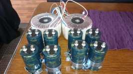
How much does a piece ??? SAMWHA 22000/100V
TME-14€ piece
GT2A229M51100SB SAMWHA - Kondenzátor: elektrolytický | TME Slovakia s.r.o. - Elektronické sú?iastky
TME-14€ piece
GT2A229M51100SB SAMWHA - Kondenzátor: elektrolytický | TME Slovakia s.r.o. - Elektronické sú?iastky
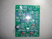
spooky iPS
Hi guys, running into a bit of trouble. Spooky IPS D8 is not lighting up?. Any advice where to start trouble shoot?. Also when i tried to measured R28 or R29 current then the LED light up?. My other board D7 is not on either?.
Quan
Hi guys, running into a bit of trouble. Spooky IPS D8 is not lighting up?. Any advice where to start trouble shoot?. Also when i tried to measured R28 or R29 current then the LED light up?. My other board D7 is not on either?.
Quan
Last edited:
Check the obvious stuff first, orientation, part values. ect. Next, compare voltages in the circuit between the positive side and the negative side.
Voltage drop across R25 should be close to the same as R29. If R29 voltage drop is high, you likely have excessive current flow through Q13/Q14.
Voltage drop across R25 should be close to the same as R29. If R29 voltage drop is high, you likely have excessive current flow through Q13/Q14.
I had some LEDs where the flat on the package was not the cathode. Verify your polarity with a meter.
- Home
- Amplifiers
- Solid State
- SlewMaster Builds