OK then, i will omit C114, leave r113 as 1K 1W and pulled out r 110 later and report back then.
Quan
Hi guys, pulled out r110 , r113 =1K , bias LED is on but still no current through 22R resistors with trimmer max out already. Not sure what what else to check for. I will have to double check all resistors and placement with the Mosfet schematic as posted by Valerys.
Quan
What's the voltage across the PD / ND terminals (this tells us your bias spreader voltage), and does it change with the adjuster? We may just have to alter another resistor in the bias generator. Resistor R107 may need to be increased in value. Valery and I settled on 680R as shown in Valery's modded schematic.
Glad to hear all is OK with you OS.
Quan, On my mosfet build on the previous board r113 is 500r. Not sure if this makes a difference.
Also 680r for r107
Quan, On my mosfet build on the previous board r113 is 500r. Not sure if this makes a difference.
Also 680r for r107
Last edited:
The R113 value isn't really too critical, anything between 470R and 1K will be fine. That value primarily determines the standing current in the driver stage, so if heating is no issue, the more the better. For the purposes of getting the circuit up and running quan's 1K is just fine and if he want's to change it later it shouldn't alter things any significant amount.
What's the voltage across the PD / ND terminals (this tells us your bias spreader voltage), and does it change with the adjuster? We may just have to alter another resistor in the bias generator. Resistor R107 may need to be increased in value. Valery and I settled on 680R as shown in Valery's modded schematic.
Ah, r107 =390 as the original schematic. I will change to 680R and report back.
Quan
New OUT pcb not match component numbers exactly as post #1131 so it's a little confusionThe R113 value isn't really too critical, anything between 470R and 1K will be fine. That value primarily determines the standing current in the driver stage, so if heating is no issue, the more the better. For the purposes of getting the circuit up and running quan's 1K is just fine and if he want's to change it later it shouldn't alter things any significant amount.
here😕
Last edited:
Point taken. I know there was a couple resistor component designators that were swapped in at least one of the newer schematics but I'm pretty sure jwilhelm issued a corrected drawing with more information especially around the implementation of options. I will try to find it and link it in the first post here.
Flexibility is really nice, but confusion needs to be headed off. Fast.
Flexibility is really nice, but confusion needs to be headed off. Fast.
There's a couple resistor values that need to be corrected in the schematic I posted when installing fets. I would appreciate it if someone could double check everything on the schematic. Once I know everything is correct I will repost it in both threads. http://www.diyaudio.com/forums/solid-state/260268-slewmaster-builds-109.html#post4422418
Hey Jeff, enail me the DipTrace file and I will get it verified later this evening. Then we can post up a 'definitive' schematic for the v3 circuit and options.
What's the voltage across the PD / ND terminals (this tells us your bias spreader voltage), and does it change with the adjuster? We may just have to alter another resistor in the bias generator. Resistor R107 may need to be increased in value. Valery and I settled on 680R as shown in Valery's modded schematic.
Hi Jason, removed r110, r113=1K,c114-empty, r107=680. There is no current still through R111 or r112. The voltage btw PD/ND terminals start from 9.6V and reduced to 7.2V as trimmer maxed out.
Quan
Hi Quan,
The current through R111 and R112 will be very small and isn't something we are looking to measure (these are the driver base stoppers). You want to measure across the output emitter resistors (or in the case of MOSFETs the source resistors), the 0R22 ones (R126 through R135) to check for quiescent current in the same way as the BJT OPS you built before. Measure across the 0R22 connected to the output pair you have installed. You should see voltage across R113 that is a little lower than the total spreader voltage measured at the PD ND connections.
The spreader IS working and giving what should be a suitable range of adjustment. I think you are attempting to measure the wrong location, unless I'm misreading you.
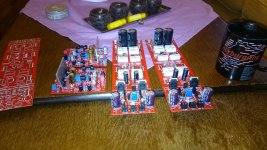
-post 1102Just a few more pictures.
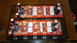
Hi Jason, i have installed only one pair of Ouput and measures the voltage across the 0.22R as in the picture but no readings. Should i measure any other readings else where to verify the circuit is working ?.
Quan
Trace out the board, you are measuring across the wrong 0R22 resistors. Move your probes over one set.
Trace out the board, you are measuring across the wrong 0R22 resistors. Move your probes over one set.
Jason, once again thanks for your help. You know what, i feel like a bloody idiot. Just to say never to make an assumption. I thought -last output pair would correlate with the corresponding emitter resistors. How wrong!!!. I am glad it is all sorted now. I just biased slowly to test it-10mA only. I will follow the procedure as outline previously earlier in the thread. Aim about 90mA ?.Thanks Jason.
Quan
Hi quan,
No worries, I'm sure if I hadn't spent some time really looking at the layout I would have made the same assumption. I missed the clue in your pictures, so I could have noticed earlier but apparently did not.
Either way, we still had to sort the bias generator. For bias, I believe Valery tested and got the best result at 90mA. That is in the ball park of suggested biasing seen elswhere, so the 90-100mA target I feel is good.
I bought two used transformers that was supposed to be 2x55v 750VA for a 5p dual mono build with 5 p ops (njw or sanken). I tested the transformers and found out they were only 2x44v with 240v mains, so I guess this is a 2x40v 230v transformer.
Will these be suitable for 5p ops? I'm going to run it on 8ohms speakers.
Will these be suitable for 5p ops? I'm going to run it on 8ohms speakers.
- Home
- Amplifiers
- Solid State
- SlewMaster Builds