That is wonderful!Maxwell,
I would take Evan's offer of the extra devices he has ordered and the cost of sending them to you by mail will more than make up for the distance from the US to your country. Many here would gladly order your parts locally with their own orders and send you the parts, if they are in a small letter sized package they should not get caught up in any customs checkpoints. You really are looking at small parts.
I wish many guys can offer this way to us who can't find parts in our place.
I see many cheap parts in the USA. These parts are exotic for us and there isn't any way receiving these.
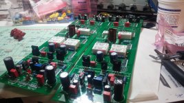
I want to say a BIG thanks to those who helping me with PCB.🙂
Last edited:
OS,
Is there ever a place for the higher powered leds, with their higher forward voltage ratings? I have seen in some schematics where a series of diodes are used, not a single diode but up to three in a row, I assume to share the load but could be wrong on that. Does this also apply to multiple leds or are the devices so different in actual use that you wouldn't string the leds like that?
ps Hope you got or get my mail soon. it should have been there by now I thought.
Go all the way , 80V rails 1000va - "arc welder mode"Question on what exactly to build for the following speakers ->
http://www.mrhifi.fi/pdf/tannoy/Dimension.pdf
I've got the TD8 and TDC1. Max rated peak power for TD8 is 375 watts and for TDC1 is 480 watts.
both can be biamped which I'm looking to do, I can wait on OS for the tweaked Kypton-ND all in one for high frequency but what to use for LF. I've got 2 x 1200 watt 18" Subs as well.
Suggestions on IPS and Power to use for the slews ?
-TJ
5 pairs of the sankens and 15A fuses. 600W can't hurt.
One pair of MT-200 on a Japanese amp alone is 125W/8R .
Kind , many red led's in a row is for voltage. A red is a 1.7V
"zener" (close) - with NTC. Two in row (like the kypton ND) is 3.4V
for the Cascode with 2X that NTC.
As far as current rating , IPS leds ... I design 1.5-2ma forward
current. The OPS FET option red would see 4ma.
Why led's ?
- I like them ... can see if your circuit works- visually.
- 2 x1.7 or 3.2V (blue) would take 6 regular diodes to match Vf.
- A red at <3ma should last 50 years.
- dirt cheap !
OS
I have good experience with mjl4302 + 2sc4159 + 2sc3601 (now 2sc3501 predriver and vas instead of 2sc3601)
Can't wait to finish my slewmaster and kypton C🙂
Can't wait to finish my slewmaster and kypton C🙂
Hi Pete,
I have a couple of questions.
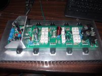
In the pic you posted showing the two different arc welder boards, you have all the emitter resistors mounted, even on the board with three pair of Sankens. Do you have them all tied in somehow?
Also, you have 1/2w resistors installed for the base stoppers. When I run the Ltspice file I don't see anywhere near 1/4W across those. What is the reason for using 1/2W there?
Thanks, Terry
I have a couple of questions.
In the pic you posted showing the two different arc welder boards, you have all the emitter resistors mounted, even on the board with three pair of Sankens. Do you have them all tied in somehow?
Also, you have 1/2w resistors installed for the base stoppers. When I run the Ltspice file I don't see anywhere near 1/4W across those. What is the reason for using 1/2W there?
Thanks, Terry
Hi Pete,
I have a couple of questions.
In the pic you posted showing the two different arc welder boards, you have all the emitter resistors mounted, even on the board with three pair of Sankens. Do you have them all tied in somehow?
Also, you have 1/2w resistors installed for the base stoppers. When I run the Ltspice file I don't see anywhere near 1/4W across those. What is the reason for using 1/2W there?
Thanks, Terry
Nope , I was just showing two possible configurations. I would of showed
the "full monty" , but I only have 3 pair MT200.
Both will be my NJW "little guys" (200W).
1/2 W basestoppers - Many things on the slew are way over-rated.
Edit - way over-rated = no thermal cycling with load ...
These resistors could pass closer to 1/2W with a short or 1R load.
1/2W just assures that they will not be a weak link. Use 1/4W if
you like - I just used what I had.
I used the caps I had - 470/100/100 for the electro's , and all
my old 10R's for the 2W resistors.
I'm about to tap today - all USA tools - extrusion. Hope it works out.
OS
Last edited:
people will say "it's easy"...but tapping sucks. One mis-twist...the tap breaks and all 19 holes all ready done are wasted time.
people will say "it's easy"...but tapping sucks. One mis-twist...the tap breaks and all 19 holes all ready done are wasted time.
There's definitely an art to tapping aluminum. It starts with proper drilling. Heat control is the key. If you get aluminum warm anywhere in the process the tap will bung up and break.
I used to use 4-40 screws and I broke taps too often. I switched to 3M screws and have not broken a tap since. Maybe the finer threads give the tap a little more mass. Be sure to use oil and clean the tap after each hole. It is also important back off 1/2 turn every revolution or so to break off the burr.
If you use tri-lobed thread rolling machine screws no tapping necessary, just drill hs with specified drill size. Added benefit is enough friction that they will not vibrate loose. Also make good taps for normal machine screws, just back them out and insert regular screws. Haven't used standard tps in years, too easy to break in work even when reversing to free chips. 5-40 works great for plastic outputs.
Hi Guys,
As pointed out in the group buy thread, There was an error in the part numbers. Here is a corrected schematic to match the screen print on the arc welder borads.
http://www.diyaudio.com/forums/atta...38-slewmaster-project-boards-v3-corrected.gif
Blessings, Terry
As pointed out in the group buy thread, There was an error in the part numbers. Here is a corrected schematic to match the screen print on the arc welder borads.
http://www.diyaudio.com/forums/atta...38-slewmaster-project-boards-v3-corrected.gif
Blessings, Terry
I have to check it. My work still continue....
22k has two red stripes on the end. Your R109 does not. I can't see the colors well enough to see if R102 is right or not.
Go all the way , 80V rails 1000va - "arc welder mode"
5 pairs of the sankens and 15A fuses. 600W can't hurt.
One pair of MT-200 on a Japanese amp alone is 125W/8R .
OS
Ok it seems the more power the better...although again I've got Toroids that will put out 67v after rectification.
Looking for feedback on what IPS to use for LF ... I guess Kypton-ND as well since I'll crossover to the subs @ 80Hz.
Will go with the MT-200's 2SC2921/2SA1215 for Output devices, 2SC2837/2SA1186 for Drivers and KSC3503/KSA1381 predriver VAS.
At some point OS I will do a full on full power arc-welder to replace my aussie amps or at least compare the two. Could the Arch welder and any of the IPS be made to take 110v so I can reuse my 2KVA toroids ?
Is anyone doing a GB on the Kypton-ND IPS as it currently stands?
If you use tri-lobed thread rolling machine screws no tapping necessary, just drill hs with specified drill size. Added benefit is enough friction that they will not vibrate loose. Also make good taps for normal machine screws, just back them out and insert regular screws. Haven't used standard tps in years, too easy to break in work even when reversing to free chips. 5-40 works great for plastic outputs.
Best advise in a Looong time 🙂
Hi guys, i am still waiting for my boards to arrive. I am still deciding to go FET or BJT?. I had one BJT amp already playing beautifully thus lean over to FET route. I have read through the thread and there was mentioning matching of the FETs was required?.
Quan
Quan
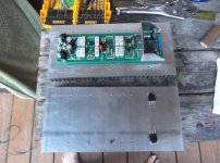
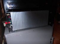
All tapped out ...
OH ! I hate tappin'
(perfection - below 1) 100mm distance between rows will allow TO-264
MT-100 or TO-3P , two extra holes for ground and thermal protection
and the main vbe to-126 .... whewwhhhh !
NO broken nothing with all USA material/tools and JW's advice.
In fact , the easiest tappin' i've ever done. Extrusions fit
the Chinese case with 25mm extra space in the front/back .
25mm HW store angle will fit exactly. (below 2).
Now to the part I really really like .... getting it working and
jammin' at 200W !! 😀😀
PS - I need a glass of wine (or shine) after that "stress" ...
OS
Attachments
Ok it seems the more power the better...although again I've got Toroids that will put out 67v after rectification.
Looking for feedback on what IPS to use for LF ... I guess Kypton-ND as well since I'll crossover to the subs @ 80Hz.
Will go with the MT-200's 2SC2921/2SA1215 for Output devices, 2SC2837/2SA1186 for Drivers and KSC3503/KSA1381 predriver VAS.
At some point OS I will do a full on full power arc-welder to replace my aussie amps or at least compare the two. Could the Arch welder and any of the IPS be made to take 110v so I can reuse my 2KVA toroids ?
Is anyone doing a GB on the Kypton-ND IPS as it currently stands?
Use a higher Voltage driver. Even at 67V , why risk 2300W of output
devices with a 150V part ? 1294/3263 sanken's for drivers ~~~ 230V.
surges happen.
Edit - yes ... with 160V electro's and all 230V+ semi's , 110V rails
are possible. IPS's have been simulated at 135V rails !! You could drop
The multiplier divider to any level to feed the IPS.
8R optimum is 75-80V 4R optimum is 65-70V. This is where you could
get the biggest peak and still retain enough SOA on the outputs.
Semelab outputs still have 3A+ DC SOA each at >90V rails , even better than the MT-200's. At 70V , they are similar.
Edit - did I read that right ?? "Replace Aussie amp" - I'm flattered !!
OS
Last edited:
Better have three or four glasses to catch up...PS - I need a glass of wine (or shine) after that "stress" ...
OS
Got most of my boards stuffed. Now I have to do the work you just finished.
- Home
- Amplifiers
- Solid State
- SlewMaster Builds