Even as I recommend yours and Val's creation every chance I get , very few
show enthusiasm. 😕
They still either go on with assorted eBay china modules or try to "re-invent"
the wheel. Perhaps the use of the micro scares them off.
Alright for their phone,but not for their precious audio.
My thoughts for the "solid state breaker" is from a serial resistance standpoint.
While a fuse can get to 100's of milliohms internal resistance , the MOSFET
gate can be much lower. It's milliohms also do not fluctuate with current.
I wonder whether a manual resettable type FET could just be made to
simply replace the fuse -period. If the 10-15A fuse would burn , you have
scorched outputs anyway , to hit a button (after you replace the semi's)
would have to occur regardless.
The protections over-current will protect against just a temporary event
that would not usually permanently damage the whole output stage.
The fuse safe-gaurds in the event of permanent catastrophic failure.
PS - the over-current protect across the Re's would not trip for a shorted
cap or screwdriver/probe slip ??
OS
Last edited:
A slipped screwdriver will usually cause dc offset or a rail voltage will drop causing the protection to activate.
I see what you are saying with the masses cringing at a microcontroller though. Most of those softstart circuits look scarier to me.
We should be able to self contain a circuit for this but it should likely be smt to keep the size in check which wiĺl again make everyone squirm. The other problem I can forsee right from the start is the need for either some resistance or a coil for current sense. I'll see what I can come up with.
Hi Jeff, how are you doing with those smd protection boards. I would be interested in a couple if it is ready .
Quan
Quan
Hi Jeff, how are you doing with those smd protection boards. I would be interested in a couple if it is ready .
Quan
I'm half way through getting the first prototype running, but haven't had enough time to finish yet. I've gotten the arduino bootstrap loaded and jumper wired it to an Uno and got software loaded onto it. The usb interface is giving me problems.
Hello,
i have a question about the power supply of the slewmonster. I want to use a SMPS.
The output power shall be 200 watts per channel into 8 ohms. Into 4 ohms, it should be 300 watts. The selected SMPS can afford 13,3A. (75 Volt output voltage) There are for each channel 13,3A / 2 = 6.6A available
6,6A / 1,41 = 4,7A Effectiv
4,7A *4,7A = 22,1
22,1 *8 Ohm = 176 Watt max per Chanal
According to my calculations, the SMPS is too weak.
But in the description of the SMPS a Class D amplifier with 2 * 800 watts is operated. make I a mistake?
Best regards 🙂
Gerd
A slipped screwdriver will usually cause dc offset or a rail voltage will drop causing the protection to activate.
I see what you are saying with the masses cringing at a microcontroller though. Most of those softstart circuits look scarier to me.
We should be able to self contain a circuit for this but it should likely be smt to keep the size in check which wiĺl again make everyone squirm. The other problem I can forsee right from the start is the need for either some resistance or a coil for current sense. I'll see what I can come up with.
what we want to do is eliminate the series resistance down to just a
DMOS junction. Up till now you would need at least a 100m ohm "sense"
resistance to directly measure current.
Look to the industrial (even electric car) industry. Jerkhead elon Musk uses
this stuff in the tesla - ACS712ELCTR-30A-T Allegro MicroSystems, LLC | 620-1191-2-ND | DigiKey
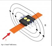
That type has 4 of the SOIC pins as a 1mOHM conductor and the other 4
as the supply / sensor. Some others are where you mount the soic right
over a trace , with the hall sensor sensing the PCB trace directly under it (below).
Neat , cheap (1-2$) - in tandem with a power mosfet could make a dual
use voltage output current monitor AND resettable fuse (latching circuit).
I'll look at more application circuits , Many to choose from ! 😎
EDIT - a slipped screwdriver on my PS will make the screwdriver explode into molten metal
without much of a rail drop.
OS
Attachments
Last edited:
I was thinking a little bigger to keep the resistance down. http://www.farnell.com/datasheets/1934117.pdf
I ran it already. Output voltage goes positive from 2.5V on forward current flow and goes negative on reverse current flow. It would have been easier to make a bidirectional unit if it went positive with any direction of current flow. If we feed this to the inverting input of an op amp and have an adjustable voltage reference on the non-inverting input we can easily set current limits. We'll likely need to slow down the output from the sensor. This thing would have a hair trigger. The output from the op amp would be able to directly feed the optocoupler to run the mosfet. We just need to regulate rail voltage to +5 and whatever the op amp needs and bring a ground to it. I'll breadboard a circuit later today and draw up a schematic to explain all this gibberish.
The next issue will be selecting a current threshold. Because of the speed of this unit we will need to limit current at a much higher limit. We will loose some constant current protection to gain speed. We will likely need to select maximum SOA current for the output devices instead conventional wire current limits. For proper protection these types of circuits are used with a fuse in series, which defeats the purpose.
Last edited:
I was thinking a little bigger to keep the resistance down. http://www.farnell.com/datasheets/1934117.pdf
I ran it already. Output voltage goes positive from 2.5V on forward current flow and goes negative on reverse current flow. It would have been easier to make a bidirectional unit if it went positive with any direction of current flow. If we feed this to the inverting input of an op amp and have an adjustable voltage reference on the non-inverting input we can easily set current limits. We'll likely need to slow down the output from the sensor. This thing would have a hair trigger. The output from the op amp would be able to directly feed the optocoupler to run the mosfet. We just need to regulate rail voltage to +5 and whatever the op amp needs and bring a ground to it. I'll breadboard a circuit later today and draw up a schematic to explain all this gibberish.
Ahh , we think alike. I was thinking a zener to knock the rail down to
12V and a 5 V pre-regulator to power the sensor and op-amp.
"Gibberish" ? , the ineffective tangents that some others pursue might
be in that realm. Here , we will eliminate the serial resistance of the
20'th century fuse in one move. This is one real world solution that will
improve the current feed into our "hungry" power amps.
PS - don't even think what you say is gibberish to me. I was a process
engineer , quite easy to to wrap my head around this type stuff !
OS
Last edited:
Another factor to think of .... have both SS fuses "trip" at the same time.
Either rails sensed fault would trip the other rail. Having just one rail trip
increases the likeliness of possible circuit damage.
Just a thought .
OS
Either rails sensed fault would trip the other rail. Having just one rail trip
increases the likeliness of possible circuit damage.
Just a thought .
OS
This thing will likely cost $20/rail is the other drawback. Small price in my books but others might see it differently.
This should also have an optional input from the Protection Board. Maybe make the power source for the control circuit optional between a zener shunt or a 12V input from the Protection Board?
This should also have an optional input from the Protection Board. Maybe make the power source for the control circuit optional between a zener shunt or a 12V input from the Protection Board?
Another factor to think of .... have both SS fuses "trip" at the same time.
Either rails sensed fault would trip the other rail. Having just one rail trip
increases the likeliness of possible circuit damage.
Just a thought .
OS
I'll experiment with the ASSR optocouplers. They are dual units. If we series one half from each rails optocoupler input with the other rail's, it may take care of this for us. Four more wires to connect though.
Attachments
Last edited:
This thing will likely cost $20/rail is the other drawback. Small price in my books but others might see it differently.
This should also have an optional input from the Protection Board. Maybe make the power source for the control circuit optional between a zener shunt or a 12V input from the Protection Board?
That's why I picked the cheaper ACSxxxx - just $1.80. The ones that just
sense a track are cheaper than the ones that have an integrated
"sensed buss".
Shop around ....
OS
That's why I picked the cheaper ACSxxxx - just $1.80. The ones that just
sense a track are cheaper than the ones that have an integrated
"sensed buss".
Shop around ....
OS
We could look at them as well. I have samples of the other to experiment with though.
Those ACSxxx sensors are the smaller version of the one I was looking at. They have an in and out pin for sensing, not off the trace below, and they are the same price if bought singly. I'll do some more searching.
I've found a couple that sense current off a trace but they are the same cost and need to be calibrated. The prepackaged module looks easier to work with.
Another consideration is stray magnetism in the amplifier. I wonder how much it will effect the accuracy?
Another consideration is stray magnetism in the amplifier. I wonder how much it will effect the accuracy?
I wonder, if 21'' century protection board is a good choice why you go for other solution?In any case please use cheap parts if it's possible.
21'' century protection board is an expensive solution.
21'' century protection board is an expensive solution.
I wonder, if 21'' century protection board is a good choice why you go for other solution?In any case please use cheap parts if it's possible.
21'' century protection board is an expensive solution.
Low RDS Mosfets are always going to be expensive. This is meant to be an upgrade for fuses to go along with other protection circuits.
Hi Guys,
I don't mean to be a wet blanket, but this thread's purpose was to discuss building the various boards that come from the group buy. Jason worked hard to keep it that way so it didn't get filled with a lot of disjointed discussions. This was to make it easier to search through. Could you please take the discussion of the protection circuit to the protection thread so we can keep this thread on topic?
Thanks, Terry
Help plse, For a fet output does the gate protection diodes have to be the one's that's suggested on the schematic or can a 4148 and a 12v ordinary zener be used ? For C107, does the writing in red means it's a 35uf 50V cap or is it the voltage of the cap that can be used. Will mje's be ok for Q107/108 and last question, for R114/115 a 10 Ohm 1watt resistor should be used.
Do I understand this all correct ! I don't want to make unnecessary mistakes.
Thanks a lot.
Do I understand this all correct ! I don't want to make unnecessary mistakes.
Thanks a lot.
Help plse,
1. For a fet output does the gate protection diodes have to be the one's that's suggested on the schematic or can a 4148 and a 12v ordinary zener be used ?
2. For C107, does the writing in red means it's a 35uf 50V cap or is it the voltage of the cap that can be used.
3. Will mje's be ok for Q107/108 and last question,
4.for R114/115 a 10 Ohm 1watt resistor should be used.
Ok ... post your questions by #'s please (see above).
1 .Yes , 4148 can do 2A surge@ 75V 914 is bit hardier - but I doubt you will
need it.
I put the bigger diode spacing there for any small/medium diode (9mm).
Zener is 500mW-1W 12V standard. The smaller 500mw will fit the 6mm
zener pads. 1W , you might have to form the leads ( I fitted one).
2. C107 would see max of 7V for VFET's and 3.4V for BJT. So , 16 -50V
could be used. I'm using a 1uF film 50V , electro would also work.
3. MJE's , not 340/350 ! - they would be pin reversed ECB. Suggested
is the MJE15032/33 or the 2sa/sc toshiba (BCE).
4. You could go either 1 or 2W. Those flameproofs of mine are 2W.
You won't use as much current with a MOSFET output stage.
OS
- Home
- Amplifiers
- Solid State
- SlewMaster Builds