Hello..i just bought some 2SC4793,2SA1837 manufactured by ISC semiconductors Inchange Semiconductor,Power Transistors,Transistor Manufacturer .Also i bought some MJE340 made by CDIL . Semiconductor Manufacturing Company | Continental Device India Ltd (CDIL)
How reliable are these manufacturers compared to Onsemi or Toshiba or STmicro?
How reliable are these manufacturers compared to Onsemi or Toshiba or STmicro?
Spooky capacitors voltage rating
Hello,
I'm building the Spooky IPS and I have a rather dumb question.
What should be the voltage rating of 0.68uF capacitors across blue LEDs (C9, C10)?
My limited knowledge says, that those capacitors don't see higher voltage than the forward voltage of the LEDs so even 50V is plenty. Right?
I'd rather be safe than sorry.
Thank you
Stefan
Hello,
I'm building the Spooky IPS and I have a rather dumb question.
What should be the voltage rating of 0.68uF capacitors across blue LEDs (C9, C10)?
An externally hosted image should be here but it was not working when we last tested it.
My limited knowledge says, that those capacitors don't see higher voltage than the forward voltage of the LEDs so even 50V is plenty. Right?
I'd rather be safe than sorry.
Thank you
Stefan
Those capacitors can be lower voltage types as you are correct, they only 'see' Vf of the LEDs. They are small in value, so getting higher voltage ratings won't cost a real penalty in size. I ended up using 1uF 100V film in those locations.
Those capacitors can be lower voltage types as you are correct, they only 'see' Vf of the LEDs. They are small in value, so getting higher voltage ratings won't cost a real penalty in size. I ended up using 1uF 100V film in those locations.
Thanks Jason,
I have 0.68uF 63V but was afraid to use unless some more experienced builder approves. And I'm glad I was not totally off in my thinking...


Have the boards ....
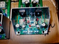
Now for the "swap"..
(note the photo below).
No real issue with the boards - just (about) perfect !
Euros are tight but fit perfect.
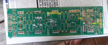
On the pix ,
- output coil will have to be wound on a AAA battery , slightly less diameter than
envisioned. 20+ turns 16-18ga will do.
- make sure you jumper the led near the Vbe hole for a BJT OPS.
- The Vbe main cap will only accept a 2.5mm lead spaced 10-22uf electro.
Actually - the electro is best for the Vbe (ESR wise).
All the other component types fit flawlessly , the 1/4w resistors , big and small diodes-
PERFECT !
Tried 12 , 16, 18mm decoupling caps , all fit perfect.
Driver heatsink drilling is slightly off from the V2.x boards - no big deal.
Outputs line up with the old board perfectly , just 4 more holes
on the extrusion - done !
It's a shame I'll have to "harvest" my present boards , they have worked so
flawlessly for over 6 months. 🙁 wish I could find them a new "home".
OS
Now for the "swap"..
(note the photo below).
No real issue with the boards - just (about) perfect !
Euros are tight but fit perfect.
On the pix ,
- output coil will have to be wound on a AAA battery , slightly less diameter than
envisioned. 20+ turns 16-18ga will do.
- make sure you jumper the led near the Vbe hole for a BJT OPS.
- The Vbe main cap will only accept a 2.5mm lead spaced 10-22uf electro.
Actually - the electro is best for the Vbe (ESR wise).
All the other component types fit flawlessly , the 1/4w resistors , big and small diodes-
PERFECT !
Tried 12 , 16, 18mm decoupling caps , all fit perfect.
Driver heatsink drilling is slightly off from the V2.x boards - no big deal.
Outputs line up with the old board perfectly , just 4 more holes
on the extrusion - done !
It's a shame I'll have to "harvest" my present boards , they have worked so
flawlessly for over 6 months. 🙁 wish I could find them a new "home".
OS
Attachments
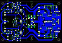
Just stuffed all the passives. R108 and 109 are swapped. Perfect layout , just had
to swap numbers on the schematic (below).
On these boards , I do notice a hairline etching error on the mosfet "option B"
smd pads (top side - near Q106). this is not on the sprint artwork .
Mosfet builders look this over , worst case you can just jumper B-E on Q105/106.
Other than this , all else seems 100% - I'll have mine running tomorrow.
OS
Attachments

Coil calculation -
18 turns / 25mm long / 12mm diameter - tested on my LCR = 1.55uH
Made them (below) with a standard AAA battery.
Now , everything else has to be harvested off my old boards.
Soldering the fastons was cool , the masks I used formed fat "landings"
for the terminals - you could never break one of these off (tough).
Also , on this board-G1 hooks to G2 (with fastons) , no wire under the board.
If you must , G2 could also go to the chassis star.
I just used 470u/100u/220u for my main/driver/multiplier decouplings.
Any MT-200 builders should go 1Ku/470u/220u (maximum capacitance).
Good to go - must sleep !
OS
Attachments
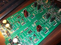
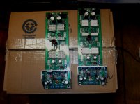
Woke up ....
Oh man , I hated "harvesting" my old slewmaster's.
(Below) But , now I know all hole diameters and spacings are correct.
The old boards took some mighty heat and no pads fell off , I think these
new PCB's are the same source. Taking some components out , even after
solder sucking , was a real PITA.
Everything lines up perfect with the old extrusion drillings. Outputs are
the PCB mounting , no need for spacers - just 11 holes. (I already have 9
existing that line up.)
V3 was MUCH easier to stuff than V2 , a lot more room around the components for my fat fingers. 😀
A spooky "drivers only test" at 50V rails is tomorrow (finish).
OS
Attachments

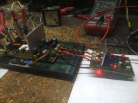
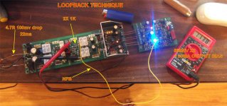
Loopbacks done - 1 pair outputs (AOK)
They pass the test. Another member is sending me new outputs , so
I'll wait on all 5 pairs for today. Tested with one pair to assure proper
operation.
Besides looking GREAT , testing went well. No cursing , exact perfection
like the last OPS.
The operation is so close to the last PCB's , the bias even stayed at 59ma.
This was what I tested before tearing my amp apart !
Good to go !! VFET uses the same tracks with just small changes and a added LED ,
so no issue there , either.
Ease of construction is the definite advantage of this OPS. I'm sure
thermals will be 100% better (with any outputs).
As Carlos (DX) would say .... "Corporation approved" 😀 .
OS
Attachments
No exploding caps?They pass the test. Another member is sending me new outputs , so
I'll wait on all 5 pairs for today. Tested with one pair to assure proper
operation.
Besides looking GREAT , testing went well. No cursing , exact perfection
like the last OPS.
The operation is so close to the last PCB's , the bias even stayed at 59ma.
This was what I tested before tearing my amp apart !
Good to go !! VFET uses the same tracks with just small changes and a added LED ,
so no issue there , either.
Ease of construction is the definite advantage of this OPS. I'm sure
thermals will be 100% better (with any outputs).
As Carlos (DX) would say .... "Corporation approved" 😀 .
OS
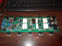
No exploding caps?
I learned my lessons well . I take the magnifying glass and actually read
the values instead of assuming size=value. 😱😱
Hooked one pair of MT's to it ... cap multipliers had NO ripple. Driver CRC
on this OPS is 10X the V2. Spook worked just as good as the wolverine,as well.
Lots of room for probes / fingers. This one has a real "business" look to
it.
I can say this will be the last/final Slewmaster.
I really like it !
OS
Nice work!They pass the test. Another member is sending me new outputs , so
I'll wait on all 5 pairs for today. Tested with one pair to assure proper
operation.
Besides looking GREAT , testing went well. No cursing , exact perfection
like the last OPS.
The operation is so close to the last PCB's , the bias even stayed at 59ma.
This was what I tested before tearing my amp apart !
Good to go !! VFET uses the same tracks with just small changes and a added LED ,
so no issue there , either.
Ease of construction is the definite advantage of this OPS. I'm sure
thermals will be 100% better (with any outputs).
As Carlos (DX) would say .... "Corporation approved" 😀 .
OS
Where you get these non flammable resistors?
Attachments
OS,
And here I thought that comment about adding in the protection circuit would mean a next revision. So your going to leave all as is, this is it?
And here I thought that comment about adding in the protection circuit would mean a next revision. So your going to leave all as is, this is it?
I think those are Mouser stock (I've seen them) , JWilhelm would know ??Nice work!
Where you get these non flammable resistors?
Kind -
Adding the whole protection to the PCB ....NAH !
The over-current euro is there. This PCB has the main fuses in-line ....
A neato thing to do here would be to make JW's "electronic fuses" (MOSFET)
on a daughter card to plug in the fuse holders. That would be the only
real upgrade possible to this beauty.
Those 10-12A fuses I use now will still do the job. 5 pair NJW/3 pair
MT-200 will easily survive with just these fuses. A 5 pair MT would
need 15A. I don't think you could burn a 5 pair !!
Now both the output DC and overcurrent are closely tied to Vzaichenko's
"21'st century protection" Thermal is one MJE340 on the main heatsink.
Those 3 protections are quite comprehensive. I've not seen a better
setup (for DIY). The Ebay stuff is junk by comparison.
OS
OS,
I guess I misunderstood an earlier comment, I thought you were adding something beyond the connectors. I didn't think you were going to add a complete protection circuit but I thought you were adding something, my mistake.
I guess I misunderstood an earlier comment, I thought you were adding something beyond the connectors. I didn't think you were going to add a complete protection circuit but I thought you were adding something, my mistake.
I think those are Mouser stock (I've seen them) , JWilhelm would know ??
Kind -
Adding the whole protection to the PCB ....NAH !
The over-current euro is there. This PCB has the main fuses in-line ....
A neato thing to do here would be to make JW's "electronic fuses" (MOSFET)
on a daughter card to plug in the fuse holders. That would be the only
real upgrade possible to this beauty.
Those 10-12A fuses I use now will still do the job. 5 pair NJW/3 pair
MT-200 will easily survive with just these fuses. A 5 pair MT would
need 15A. I don't think you could burn a 5 pair !!
Now both the output DC and overcurrent are closely tied to Vzaichenko's
"21'st century protection" Thermal is one MJE340 on the main heatsink.
Those 3 protections are quite comprehensive. I've not seen a better
setup (for DIY). The Ebay stuff is junk by comparison.
OS
I don't remember where I got those resistors. At that point I was pretty disappointed with both Digikey and Mouser so they were likely from Newark. All three companies sell them.
I could design a mosfet relay to clip into a fuse holder but I'm not sure how secure the connection would be. I might be better to remove the fuse holders and insert leads like we did with the first version of speaker relays, or just install them in the supply.
Plenty of holes (8) and plenty of space on the PS end of the PCB.
-Are your relays self sensing ?
-Do they monitor current and trip at a set point.
-are they powered by the same rail they are protecting ?
OS
Plenty of holes (8) and plenty of space on the PS end of the PCB.
-Are your relays self sensing ?
-Do they monitor current and trip at a set point.
-are they powered by the same rail they are protecting ?
OS
The relays on the supply are controlled by the protection board. The mosfets were powered through an opto module the same way the speaker relays were. We could go more elaborate and make it all self contained but I'm not sure if we could do much better than the protection board does.
- Home
- Amplifiers
- Solid State
- SlewMaster Builds