Yes, the only hassle to making the original into a Hexfet was soldering the protection diodes to the bottom and cutting in an LED for the VBE. Should be very easy to incorporate.
My only question is what are you going to do with all that power? 😱 These are hifi not Pro sound systems. The Grateful Dead have disbanded. 😎
Not just the "flat out baddest" class AB power project , but the better thermals
will make this OPS "sing" better on smaller heatsinks or in VERY hot
conditions.
PS - The new slew would also be a great commercial power stage , as well.
Especially with IRFP or MT-200/MGxxxx's !!
OS
Brother Pete, making it IRFP-compatible would be really great! Excellent option 
In addition to Vgs zeners and a LED in the spreader, please add a couple of jumpers for easy jumpering the pre-drivers.
I also love MT-200s - a box of Sankens is waiting in my stock - now I know for what exactly 😛
In addition to Vgs zeners and a LED in the spreader, please add a couple of jumpers for easy jumpering the pre-drivers.
I also love MT-200s - a box of Sankens is waiting in my stock - now I know for what exactly 😛
Update,
I hooked it up to my 5P Slewmaster OPS. No oscillation with or without the cap. So it is related to the small OPS.
Good news!
Good news!
Yes but now I need to figure out what the issue is with the OPS. It's to cool not to be able to use. I did make some changes that may be affecting it. I will have to order the exact parts and try again.
I did not investigate it in detail, but something makes the drivers closing too slowly there - as a result they appear both open at some high-frequency signal and suffer the current shoot-through (rail to rail).
You can test it safely the following way - connect your DMM to the emitter resistors, set the bias. Leave the DMM connected. Send 1KHz sine to the input. DMM reading will increase - note the value. Gradually increase the frequency at the input - 2, 3, 5 KHz... If after 5 -10KHz you will see a noteable increase in reading - there is a problem, you are coming close to shoot-through. Just don't go higher as it will kill the drivers.
Valery
If the one driver is switching off too slow, how about biasing the predriver a bit higher (at the moment there is 1k resistor in between the drivers), let me say 680R resistor in between the predrivers ? (or add some speedup capacitor ?)
I have made measurement with no load connected and with fast sqare applied to the input the current was rising a bit, so I have increased the speed-up capacitor just by the OP transistor bases from 100nF to 470nF and the current rise was very slight.
So I will test the same with predrivers too.
What would you think ?
hmm
I am bit suprised that the resaults are so different.
Terry
I really like the small CFP-Mad IPS.
You can adjust the compensation a bit with the cliffjumper to get better resaults or test the plan B schematic from post 608 (i didnt tested it yet).
As evident by the flaming resistors.I did not investigate it in detail, but something makes the drivers closing too slowly there - as a result they appear both open at some high-frequency signal and suffer the current shoot-through (rail to rail).

I'm pretty sure it is doing what you are saying. The question is what to do to fix it.
Attachments
OS,
Your talking 500-800 watts per channel or tow channels? What would be the draw on a typical 15amp 110V circuit, will this be the actual limit that you can reach before having to move to a 20 amp circuit or will you just see some voltage droop across the tranny that will create more power supply ripple?
yes , we are at the US household limit with 5 pair MT-200's ! Get out yer'
electric range 6ga. cords and wire for 220V 2-phase 😀 .
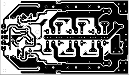
Borys , do you realize that the actual physical layout of the OPS also
contributes to it's stability ?
Post the foil side .....
OS
yes , we are at the US household limit with 5 pair MT-200's ! Get out yer'
electric range 6ga. cords and wire for 220V 2-phase 😀 .
Borys , do you realize that the actual physical layout of the OPS also
contributes to it's stability ?
Post the foil side .....
OS
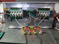
Here you go.
One note. On mine I wired it like the Slewmaster. I made the center pin ground and pulled NFB from center trace.
Attachments

os
Thanks. The top screan is in pic bellow, take a look at it please.
I am getting good resaults with thoshiba transistors.
But I have had some too much current consumption issue with no load connected at fast transients --> prapobly here is the problem.
I will investigete it further after holidays.
Regards
Attachments
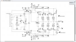
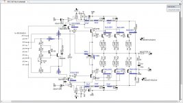
Those 100R stoppers on the pre-drivers are questionable.
R13 ,14 , and R22 are bad. Use a fast pre-driver , also ... like 1381/3503's.
C1 and 2 should be bigger with no multiplier (220u @ 100V).
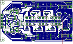
"planing the ground" has the advantage of more current but a disadvantage
of more surface area to act as the second plate of a big capacitor.
I give more "air" between traces. Empty spaces as ground just become
"antenna's" !
PS - with r13/14 in simulation , most of my IPS's glitch , ring , or even
oscillate .
OS
R13 ,14 , and R22 are bad. Use a fast pre-driver , also ... like 1381/3503's.
C1 and 2 should be bigger with no multiplier (220u @ 100V).
"planing the ground" has the advantage of more current but a disadvantage
of more surface area to act as the second plate of a big capacitor.
I give more "air" between traces. Empty spaces as ground just become
"antenna's" !
PS - with r13/14 in simulation , most of my IPS's glitch , ring , or even
oscillate .
OS
Last edited:
I looked at the Slewmasters ops and as stated, your R13,14 & 22 are not there. C3 is 680n. The pre-drivers are the same as yours MJE340/350. I'll try to get to that today. I need to find the Schematic for the 2p Slewmaster. It uses the TO-220 drivers. I wanted to see what the bias is on the drivers. I think they run hotter than yours.
Terry You can lower the biasing resistor for the drivers, 150R or 100R instead of 220R.
Thanks!!
Thanks!!
Hi Guys,
OK, I got tired of trying to get the damaged board working so I etched a brand new board and started over. I changed a few things based on the above suggestions. I jumpered R13, R14 & R22. I lowered R28 to 180R. I used KSC3502/A1381 for the pre-drivers and MJL4302/4281 for the outputs. I also changed C3 to 680n to match the Slewmaster.
Then tested. If I play sine and square waves through it with no load it works perfectly. The moment I attach a dummy load the bias shoots up very high. I tried 3 different IPS and they all do the exact same thing. I watched on my scope and I can't see anything that looks like oscillation. I basically have all the same devices that I use in the Slewmaster OPS except for using 2SC4793/A1837 for the drivers. The Slew OPS has MJW3281/1302 for the drivers. I am attaching an as-built
One other thing that may be of interest is that there is about 40mV offset, even with the Krypton C which has a servo.
Waiting for instructions.
Blessings, Terry
Attachments
Terry
Thanks for hard work.
The offset should be corrected by the servo anyway. If you are checking the bias according to the voltage drop on the emitter resistors please check if they have correct resistance (0,34R in your case I think), they may not survive too high current shoot.
The bias is rising up after dummy load connected --> with the signal not applied to the input ??
The place where excessive current is consumed must be found by checking the voltage drops at the resistors (and resistors itself).
If there is no visible signs of oscillations the excessive current must be DC somewhere.
Last edited:
Maybe I wasn't clear. If I have no load attached everything looks good. The bias adjusts fine and acts normal to sine wave and square wave input. Everything looks normal on the scope too. The moment I plug in a dummy load to the output the bias jumps very high. If I dial the bias all the way down to 0.00v and then plug in the dummy load the bias will jump to 50mV or more across a pair of the .22R emitters. I have 3, 0R68 resistor in parallel at each output. This happens even with the input shorted. I have one board built per original specs. I will try this same thing and see if it does this.
50mV across 0.22R is really a lot!
Just in case please check the resistor values with ohm meter. I have build several boards with this layout and so far so good. I am back on track on thursday so I will do the same changes on my board too.
Regards
Just in case please check the resistor values with ohm meter. I have build several boards with this layout and so far so good. I am back on track on thursday so I will do the same changes on my board too.
Regards
- Home
- Amplifiers
- Solid State
- SlewMaster Builds