Yes I know it is a lot. The issue is it jumps that high only after a load is connected. Prior to that everything looks normal. I will compare it to the other board that has all the resistors in place. I really want to get this working. I love the size.
Terry,
Am I mistaken that the difference between the output section you are now having trouble with and the Slewmaster is just a change in layout with the output devices moved closer together or is there some other changes to the circuit? Trying to follow along with what you are doing and wondering what other things besides layout has changed. Great work as always, I think I would have been a bit discouraged after a few sets of resistors went up in flames but you just keep on going. Thanks for letting the rest of us in on what you are doing.
Steven
Hi Kind,
The main differences are change in layout, TO-220 drivers and no cap multiplier. I am doing this mainly to learn so getting it working is important lest I learn nothing. Hopefully others will benefit as well from the process. Since all of the bonifide Slewmasters have been well covered and OS hasn't released another one yet it gives us something to work on. The two IPS that I just built play very nicely with the Slewmaster ops. This ops is a really nice size for someone who is limited in height as it is less than 3" tall. Bimo says his works fine so I must have done something wrong. If I can find the problem, it may help me in the future should I see this symptom again.
Blessings, Terry
Yes I know it is a lot. The issue is it jumps that high only after a load is connected. Prior to that everything looks normal. I will compare it to the other board that has all the resistors in place. I really want to get this working. I love the size.
After playing about in the simulator I suggest actually reducing the base stoppers in value. I was finding a peak when the base stoppers were too high. I have settled on output stoppers as 2R2 and driver stoppers as10R in the simulator I used 2R2 om my SlewMasters to good effect. Also stoppers in the pre-drivers don't help anything and actually make things worse, as ostripper has already mentioned. If heat is manageable you could also run the pre-driver and driver a harder by bringing down the values of R10 and R28, maybe 470R and 120R respectively. That can also help to settle things too by getting the device's into a current range where their gain is more linear.
Hi Jason,
That's interesting. My Slewmasters use 4R7 per the schematic without issue. I can't find the schematic I used for the 2p ops. It uses TO-220 drivers so those values should work on this board. I will try the values you have offered here and see what happens. Thanks again for your always kind help.
Blessings, Terry
Thanks Terry, The reason that I am very interested was because I do need to use a narrow package and this looked like one way to do that. I was considering having the output devices perpendicular to the main board on the normal Slewmaster and this way that isn't necessary. What was the intention of removing the cap multiplier if you know? I'll keep watching and see when you solve this problem. This output with a Krypton-C type input section would be as close as I think I can get to a smaller package. The 2p Slew would be my other option with the outputs turned 90 degrees from the board.
Terry
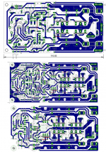
I have made another layout of the small OPS board (more air in between the traces and as advised I have removed few resistors). Will post it on Thursday.
I suspect You may have some faulty component now on the board (I could be wrong).
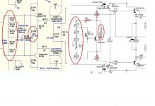
There is no signs of oscillations with load connected, bias is DC component so I think the best way is to disconnect the IPS, put back the two 15kR resistors instead.
Set the bias approx 10mV at emitter resistor, measure DC on the output --> if it is reasonable low, connect than dummy load and measure again the bias at the emitter resistor ---> this should give you some clue. To confirm measurement you can try to measure bias at the one of the supply rails - threw some small value resistor.
I have made another layout of the small OPS board (more air in between the traces and as advised I have removed few resistors). Will post it on Thursday.
I suspect You may have some faulty component now on the board (I could be wrong).
There is no signs of oscillations with load connected, bias is DC component so I think the best way is to disconnect the IPS, put back the two 15kR resistors instead.
Set the bias approx 10mV at emitter resistor, measure DC on the output --> if it is reasonable low, connect than dummy load and measure again the bias at the emitter resistor ---> this should give you some clue. To confirm measurement you can try to measure bias at the one of the supply rails - threw some small value resistor.
Hi Borys,
Good idea. I didn't think to hook up the load without the IPS in place. That will at least show if it is NFB related. I'll let you know.
Good idea. I didn't think to hook up the load without the IPS in place. That will at least show if it is NFB related. I'll let you know.
OK, I hooked the OPS up stand alone with 15K resistors from V+<PD and V-<ND. Power it up and I have .9mV at the NFB node and 0.00V at the speaker out. I set the bias to 20mV across a pair of the 0R22 emitters. I plug in the dummy load and see Maybe 1mV increase in bias. Then I power down and hook up the CFP-Madness IPS. Power back up without the load attached and see 21mV across the emitters. Plug in the dummy load and the bias jumps to 140mV. That is through the light bulb so it is likely even higher since the light bulb dials out some of the current. Again, I don't see anything on the scope. No fuzz, thickening of trace, anything. I'll try the same thing with the original circuit and get back.
This is me getting back to you. I hooked up the good board with the original circuit. I powered it up with OPS stand alone with resistors. Everything is fine as before. Then I hooked up the IPS. Everything looks good with not load. Sine and square wave look good. I plugged in the load and the bias holds steady and doesn't rise. However the square waves have 5 or 6 oscillation nodes across the top bar. They are not there with the load detached. Next I solder jumpers across R13, 14 & 22. When I power back up I have to reset the bias as expected. I checked sine and square waves and they look good. Then I plugged in the load and the 10R resistors went up in flames. I checked and the drivers are not shorted this time so at least I don't have to replace them again. I guess at this point I should wait for Bimo to test his new layout.
Terry, just as a bold idea - are you sure the OPS's ground and IPS's ground are connected properly. Otherwise, can there be sone fast short impulses, not really visible on the scope at the relatively slow scan?
I mean, if the offset is zero and the ground voltage is zero, then connecting the load does not change anything - no current through the load. So, after you connect the load, either some offset takes place, or some oscillation/impulses invoke some additional current through the output pairs. It cannot appear from nowhere 🙂
I mean, if the offset is zero and the ground voltage is zero, then connecting the load does not change anything - no current through the load. So, after you connect the load, either some offset takes place, or some oscillation/impulses invoke some additional current through the output pairs. It cannot appear from nowhere 🙂
hmm
If everything else looks good I would solder 100pF B-C caps at the drivers and see.
I am a bit confused, I was listening this OPS amp for past few weeks with 4R load without any problems (toshiba OP tranies).
I will have new layout on Thursday or Friday for tests.
Valery
Looks like the current shoot goes threw drivers but what is causing it ?
To open the drivers there is required a bit more than 2,4V between the bases, or the high current flowing threw the track on pcb is messing up the current in the track next to it.
Last edited:
I double checked the grounds. I have continuity all the way from PSU through to the input. Weird thing is I played music through it. I must have set the bias with everything connected. Of course after a few minutes the drivers shorted and fire emitted. The weird thing is that without the load it looks beautiful. I don't understand because the values I have on one of the boards is almost exactly the same as the Slewmaster yet it does this.
Terry Have you tryed to solder the 100pF caps at the drivers? I will solder MJL outputs and see why it is killing the drivers. Slewmaster uses 30mhz drivers with 400pf cob, the to220 drivers are 100MHz and very low cob. Worth of trying.
Last edited:
Hi Borys,
No I haven't. I am more interested in why the Slewmaster OPS works and this one doesn't. I use the onsemi outputs all the time in place of the 2SC5300/A1943.
No I haven't. I am more interested in why the Slewmaster OPS works and this one doesn't. I use the onsemi outputs all the time in place of the 2SC5300/A1943.
I have used exactly the same drivers as Terry (4793,1837) in my SlewMaster as drivers with MT200, 2sc3264,1295 out without any problem ,without any compensation even in pre drivers.Terry Have you tryed to solder the 100pF caps at the drivers? I will solder MJL outputs and see why it is killing the drivers. Slewmaster uses 30mhz drivers with 400pf cob, the to220 drivers are 100MHz and very low cob. Worth of trying.
Terry
That is a good question. It works fine with toshibas on my bench...
I have made several amps with this layout (but I have used compensaiton caps at the drivers with EF3, the top layers bellow). One of them is playing music every day at my home. I am looking forward to back to my lab.
I am also wondering why You are getting a bit overcompensated resaults form cliffjumper, please take a closer look at my scope reading at 20kHz@8R load, doesn't look as rounded. Heh there will be no sleep at all next few days 😀
thimios
Thanks for update!
I have some idea but will solder it at the wekend.
Regards
Attachments

Last edited:
The "father" of the slewmaster , (the HK680 EF3) uses the 4793/1837 pair !
I have 2 amps with 35mhz Ft drivers and 2 more with 60mhz Ft devices. ALL
are perfect with the 4 IPS's I've used. These Sanken's are also between
400p and 150p Cob.
But , all 4 amps use 1381/3503 predrivers (5-10p Cob).
1 amp also does not have the multipliers (my sub amp) - still perfect.
OS
I have 2 amps with 35mhz Ft drivers and 2 more with 60mhz Ft devices. ALL
are perfect with the 4 IPS's I've used. These Sanken's are also between
400p and 150p Cob.
But , all 4 amps use 1381/3503 predrivers (5-10p Cob).
1 amp also does not have the multipliers (my sub amp) - still perfect.
OS
What about the large cap across the vbe multiplier? 1u on the Slewmasters and 22u on borys'? Could this cause the lockup?
- Home
- Amplifiers
- Solid State
- SlewMaster Builds