Terry
That was some fire there , huhh..
In case of failures just 4 resistors and the drivers need to be replaced (the 4 resistors are working as a fuses too 🙂.
May OS will have some advice, maybe soldering 100pF caps in the drivers would help with that issue ?
I was playing with that setup for good few days so far and all looks fine, but I havn't tryed any of Slewmaster IPS yet (only my few boards so far)
After I come bac I will solder one of them and inspect the issue.
Regards.
Compensation differences
Hello All,
I have researched the issue and... it could be avoided if I would do it earlier 🙄
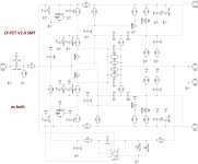
Even for IRFP-based OPS, compensation caps values are slightly different from the initial ones, designed for LFET OPS. With EF3 BJT OPS and original compensation, both gain and phase responses go absolutely crazy. This option requires much deeper compensation. So, the optimal values look like this:
LFET OPS (TubSuMo):
C12, C15: 10pF
C16, C17: 100pF
IRFP-based SlewMasters:
C12, C15: 100pF
C16, C17: 330pF
Original BJT EF3 SlewMasters (and Borys's OPS):
C12, C15: 150pF
C16, C17: 470pF
Although, for IRFP-based OPS initial values are not optimal, but acceptable, for EF3 BJT they are very bad - way too low, leaving the amp at the edge of stability.
I will test/measure the new optimal values for IRFP OPS tomorrow.
I will also copy this info to my CF-FET thread for the benefit of the members visiting that thread.
Terry - many thanks for bringing this up - I hope we all have learned something (or confirmed something we already had a clue about 🙂) today
Schematic is attached for your reference.
Cheers,
Valery
Hello All,
I have researched the issue and... it could be avoided if I would do it earlier 🙄
Even for IRFP-based OPS, compensation caps values are slightly different from the initial ones, designed for LFET OPS. With EF3 BJT OPS and original compensation, both gain and phase responses go absolutely crazy. This option requires much deeper compensation. So, the optimal values look like this:
LFET OPS (TubSuMo):
C12, C15: 10pF
C16, C17: 100pF
IRFP-based SlewMasters:
C12, C15: 100pF
C16, C17: 330pF
Original BJT EF3 SlewMasters (and Borys's OPS):
C12, C15: 150pF
C16, C17: 470pF
Although, for IRFP-based OPS initial values are not optimal, but acceptable, for EF3 BJT they are very bad - way too low, leaving the amp at the edge of stability.
I will test/measure the new optimal values for IRFP OPS tomorrow.
I will also copy this info to my CF-FET thread for the benefit of the members visiting that thread.
Terry - many thanks for bringing this up - I hope we all have learned something (or confirmed something we already had a clue about 🙂) today
Schematic is attached for your reference.
Cheers,
Valery
Attachments
Thanks Vallery
Uhh I taught that I have created a nice fireworks. There is so many virables and fun in DIY.
OS
You are absolutely right, the learning process needs mistakes I have made a lots of them but I will continue to make them 🙂
No risk no fun .
Regards
Uhh I taught that I have created a nice fireworks. There is so many virables and fun in DIY.
OS
You are absolutely right, the learning process needs mistakes I have made a lots of them but I will continue to make them 🙂
No risk no fun .
Regards
Hi Valery,
What would be the drawback to just running the values for the bjt for all of them? What does over compensation do? I'm glad I only fried this little board and not one of my 5p Slewmasters. Thanks again for always being so prompt at finding answers.
Blessings, test dummy Terry 😀
What would be the drawback to just running the values for the bjt for all of them? What does over compensation do? I'm glad I only fried this little board and not one of my 5p Slewmasters. Thanks again for always being so prompt at finding answers.
Blessings, test dummy Terry 😀
Hi Terry,
Yeah, sometimes you build faster than I think 😀
Setting these individual values I'm trying to maintain stability, keeping the circuit as fast and wide-bandwidth as possible at the same time, getting the most from it.
Overcompensation will result in rounded square wave response and overall slow-down of the circuit. Although, it would be interesting to see - to what extent, really.
Cheers,
Valery
Hi Valery,
What would be the drawback to just running the values for the bjt for all of them? What does over compensation do? I'm glad I only fried this little board and not one of my 5p Slewmasters. Thanks again for always being so prompt at finding answers.
Blessings, test dummy Terry 😀
Don't feel bad ... The slew OPS is setup for either a standard BJT or cascoded
BJT VAS. The HK680/990 are the example designs.
Running a FET VAS is quite the deviation. But this is fun ? huh .
Me and Val have most likely come up with more designs and combined just
about every OPS with every IPS than the forum has since it began.
Never before could a builder pick any amp input stage and choose
what powerful OPS (BJT or MOSFET) to run it with.
With such a wide array of choices , I'm surprised things don't burn up
more often !! 😱
OS
....
Me and Val have most likely come up with more designs and combined just
about every OPS with every IPS than the forum has since it began.
...-
OS
Some modesty won't hurt here.
With such a wide array of choices , I'm surprised things don't burn upDon't feel bad ... The slew OPS is setup for either a standard BJT or cascoded
BJT VAS. The HK680/990 are the example designs.
Running a FET VAS is quite the deviation. But this is fun ? huh .
Me and Val have most likely come up with more designs and combined just
about every OPS with every IPS than the forum has since it began.
Never before could a builder pick any amp input stage and choose
what powerful OPS (BJT or MOSFET) to run it with.
With such a wide array of choices , I'm surprised things don't burn up
more often !! 😱
OS
more often !
Me too,I'm surprised that this long travel gives to me only one pair MJL21195/21196 and one pair 2sc3264/1295 burned up.!
😀
I have blown transistors and smoked plenty resistors but this was you first time I have seen actual flames. I was going to etch a new board but I think I will leave it like this to remind me not to be in such a hurry to leave the protection of the light bulb.
There will be burning, it just' does not get reported ! 😀
Here is some modesty - I first put 35V decoupling caps in , smoked them.
Then I put the correct 100V caps in (reversed polarity) smoked them
and a whole output stage.
I screwed up twice , but now I'm listening to that poor amp .... 3 months
going strong.
PS - my eyes are going bad .. can't see the parts easily , anymore 🙁 .
Edit - forgot to screw the ground on my sub amp .... the MT-200's went full conduction and
blew the 10A fuses after making the trafo hum like hell (loaded) , that OPS survived with no
blown devices. MT-200's kick butt !!
OS
Last edited:
Well done Terry, add some excitment/action to the hobby 🙂
P.S. be careful pls.\
I remember when I worked at Motorola, Tom, was powering up a new fixture, well a big ecap was in backwards, and kaboom/pop. ecap internals were all over the lab, lots stuck to his beard. he was picking the crap out for a while, stinky stuff, unique odor for sure.
P.S. be careful pls.\
I remember when I worked at Motorola, Tom, was powering up a new fixture, well a big ecap was in backwards, and kaboom/pop. ecap internals were all over the lab, lots stuck to his beard. he was picking the crap out for a while, stinky stuff, unique odor for sure.
5 pair MT-200 OPS
If JK could give me whatever latest sprint .lay of the perfect OPS's
I have now ....
I really want to make a 5 pair MT-200 capable "Kong" slewmaster.
Most powerful (short of class H) on the forum.
5 -pair would be almost 2Kw of devices. 20A rails.
70V PS would equal 400W/8R and 700W/4R with SOA to spare.
Semelab output devices could even exceed this by 10% !!
OS
OS, I emailed you my Sprint file, some Makros and the executable file for Sprint 6. Did you not get the message / attachments? The file I sent is what was used for the production of the boards and is up-to-date and has all the boards in the one file.
All there was is sprint 6 (1) , a CFA-XH .lay(2), and a bunch of macros (in the 3rd one).
OPS's are not there.
I checked both emails , unless yahoo screwed up (or blocked something).
Edit , I did not know .... Sprint 6 is tabbed with all the files in one - you should
of told me .... 5 did not do this !
OS
OPS's are not there.
I checked both emails , unless yahoo screwed up (or blocked something).
Edit , I did not know .... Sprint 6 is tabbed with all the files in one - you should
of told me .... 5 did not do this !
OS
Last edited:
If JK could give me whatever latest sprint .lay of the perfect OPS's
I have now ....
I really want to make a 5 pair MT-200 capable "Kong" slewmaster.
Most powerful (short of class H) on the forum.
5 -pair would be almost 2Kw of devices. 20A rails.
70V PS would equal 400W/8R and 700W/4R with SOA to spare.
Semelab output devices could even exceed this by 10% !!
OS
Which Semelab devices are you talking about to do such? Would the Double Die 200 volt parts be the one?😀
Which Semelab devices are you talking about to do such? Would the Double Die 200 volt parts be the one?😀
Yes , the MG6331/9411 might do 500/800W. 2 oz PCB with a bit thicker rails
15A+ fuses and a bit more local decoupling.
I'm going to spread the output pairs out along the whole 9" of the board.
Any present build will just have to "drop it in" (same holes) ... for the Vbe and
most of the outputs. Spreading it out will allow MT-200's to be used , as well.
"king of output stages" (the kong).
OS
All there was is sprint 6 (1) , a CFA-XH .lay(2), and a bunch of macros (in the 3rd one).
OPS's are not there.
I checked both emails , unless yahoo screwed up (or blocked something).
Edit , I did not know .... Sprint 6 is tabbed with all the files in one - you should
of told me .... 5 did not do this !
OS
Sprint 5 can 'tab' multiple boards too. Just choose 'New Board' and you should get a new tab containing the blank board. I like to keep a whole project in one file so nothing gets lost. If you are so inclined to share back the file I would like to see 'Kong' when it is done.
OS,
Your talking 500-800 watts per channel or tow channels? What would be the draw on a typical 15amp 110V circuit, will this be the actual limit that you can reach before having to move to a 20 amp circuit or will you just see some voltage droop across the tranny that will create more power supply ripple?
Your talking 500-800 watts per channel or tow channels? What would be the draw on a typical 15amp 110V circuit, will this be the actual limit that you can reach before having to move to a 20 amp circuit or will you just see some voltage droop across the tranny that will create more power supply ripple?
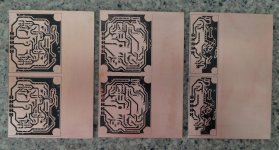
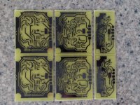
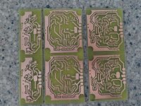
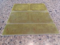
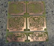
Ready to populate. I changed the layout slightly to better match up with the Slewmaster.Bellow 3 IPS boards --> files for thermotransfer, the 4th one Ill check after my holidays.
There is still some work left on all of them but they are safe to solder anyway.
IMPORTANT --> tube IPS is causing full DC at the output of the amp before cathodes are heated up so it can be used only with DC protection circuit (it needs approx 5-8s before NFB starts to correct DC).
The CFP-Mad, was tested on +/-45V psu so far.
Attachments
- Home
- Amplifiers
- Solid State
- SlewMaster Builds