guys i have seen a few board builds with this bent aluminum as a sink
is there a reason for this bent around with board mount holes verses a normal sink?
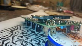
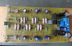
That was a heat sink design I stole from Jason for my amps. I was planning to use mine for plate amps in a subwoofer. This design stops the drivers from moving and breaking their legs off from vibration.
still4given
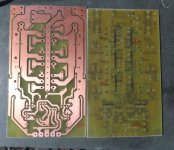
Silk mirror in atatchment, it is a bit measy but it may help a bit. I am allways printing the top layer in two times bigger scale on A4 paper sheet as a soldering helper - it is easier this way for me. I do not have spirit file, I am using eagle so I can post eagle file if U would like.
GKF
I spot that radiator on one of the slewmaster builds and it is briliant and simple idea.
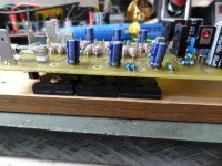
And bellow a pic how to solder/line up the transistors under the board.
The to220 devices have same thicknes as OP transistors, just ''sandwitch'' them together and grab with one hand, than solder only one leg of OP transistor, inspect and solder rest of the 2 legs. After that just tilt the transistor a bit and put the screw in.
Regards Peter
Silk mirror in atatchment, it is a bit measy but it may help a bit. I am allways printing the top layer in two times bigger scale on A4 paper sheet as a soldering helper - it is easier this way for me. I do not have spirit file, I am using eagle so I can post eagle file if U would like.
GKF
I spot that radiator on one of the slewmaster builds and it is briliant and simple idea.
And bellow a pic how to solder/line up the transistors under the board.
The to220 devices have same thicknes as OP transistors, just ''sandwitch'' them together and grab with one hand, than solder only one leg of OP transistor, inspect and solder rest of the 2 legs. After that just tilt the transistor a bit and put the screw in.
Regards Peter
Attachments
I have a question about yours valve IPS.still4given
Silk mirror in atatchment, it is a bit measy but it may help a bit. I am allways printing the top layer in two times bigger scale on A4 paper sheet as a soldering helper - it is easier this way for me. I do not have spirit file, I am using eagle so I can post eagle file if U would like.
GKF
I spot that radiator on one of the slewmaster builds and it is briliant and simple idea.
And bellow a pic how to solder/line up the transistors under the board.
The to220 devices have same thicknes as OP transistors, just ''sandwitch'' them together and grab with one hand, than solder only one leg of OP transistor, inspect and solder rest of the 2 legs. After that just tilt the transistor a bit and put the screw in.
Regards Peter
Is this compatible with OS original SlewMaster output board?
thimios
Yes it is compatible with SlewMaster. Just connection is bit different ARK vs goldpins, but you can use wires to solder them together. I putted two types compensation for that IPS, you can try both of them.
regards
Yes it is compatible with SlewMaster. Just connection is bit different ARK vs goldpins, but you can use wires to solder them together. I putted two types compensation for that IPS, you can try both of them.
regards
Thanks borys,it doesn't matter the connection way🙂thimios
Yes it is compatible with SlewMaster. Just connection is bit different ARK vs goldpins, but you can use wires to solder them together. I putted two types compensation for that IPS, you can try both of them.
regards
My question is about the capacitance multiplier included in OS SlewMaster..I don't know if current is enough for valve IPS.
Last edited:
I am usin +/-60V supply so if the supply voltage is similar all should be fine.
Valve IPS is takin very little current. VAS bias is approx 3,8mA, total requirement is less than 10mA for whole IPS.
Valve IPS is takin very little current. VAS bias is approx 3,8mA, total requirement is less than 10mA for whole IPS.
My power supply is +/-50v.I am usin +/-60V supply so if the supply voltage is similar all should be fine.
Valve IPS is takin very little current. VAS bias is approx 3,8mA, total requirement is less than 10mA for whole IPS.
I will try to add another small transformer, in series with the main transformer, to increase voltage.
Thanks borys,it doesn't matter the connection way🙂
My question is about the capacitance multiplier included in OS SlewMaster..I don't know if current is enough for valve IPS.
The only thing that would happen to the slew OPS is a slight
drop in voltage at the multipliers. You would need 100's of milliamps load to exceed
the beta of the pass transistors.
Even a MJE340/350 here would need >50ma load for that first additional volt
(drop).
OS
Thanks Pete but my power supply is +/-50v only🙁The only thing that would happen to the slew OPS is a slight
drop in voltage at the multipliers. You would need 100's of milliamps load to exceed
the beta of the pass transistors.
Even a MJE340/350 here would need >50ma load for that first additional volt
(drop).
OS
Thanks Pete but my power supply is +/-50v only🙁
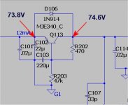
Voltage does not matter , you could reduce the base to collector resistor
on the multiplier to only have a .6 - .8V drop in the circuit as a whole.
49V+ is not too bad. Increasing the resistor to ground will have the same effect. (below example)
OS
Attachments
Thanks for tips .Borys uses +/- 60v for this Tube IPS.Voltage does not matter , you could reduce the base to collector resistor
on the multiplier to only have a .6 - .8V drop in the circuit as a whole.
49V+ is not too bad. Increasing the resistor to ground will have the same effect. (below example)
OS
What you say for the two transformers solution?I mean a small transformer about 2x9v with separate rectifier and filter in series with big one.
Thanks for tips .Borys uses +/- 60v for this Tube IPS.
What you say for the two transformers solution?I mean a small transformer about 2x9v with separate rectifier and filter in series with big one.
A boosted supply IPS was envisioned as a option for the slew (jumper on
the OPS board).
OS
still4given
Silk mirror in atatchment, it is a bit measy but it may help a bit. I am allways printing the top layer in two times bigger scale on A4 paper sheet as a soldering helper - it is easier this way for me. I do not have spirit file, I am using eagle so I can post eagle file if U would like.
GKF
I spot that radiator on one of the slewmaster builds and it is briliant and simple idea.
And bellow a pic how to solder/line up the transistors under the board.
The to220 devices have same thicknes as OP transistors, just ''sandwitch'' them together and grab with one hand, than solder only one leg of OP transistor, inspect and solder rest of the 2 legs. After that just tilt the transistor a bit and put the screw in.
Regards Peter
Hi Borys,
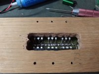
Just about ready for testing. I like your idea with using a TO-220 for a spacer but it doesn't work too well on tinned boards. I built a jig out of some oak so I could hold everything in place for soldering. I had to change a few values based on what I had in the bin. Emitters are a pair of 0R68 instead of 0R47 so I have 0R34 instead of 0R23. Should be OK but if not I will add a third 0R68. I also used 22uF for the caps on the outputs like the Slewmaster because I didn't have enough 100uF/100v. I have MJL4281/4302 in the outputs for the same reason. I plan to fly the VBE on wires and mount it on top of one of the outputs. As soon as I get that done and install the inductor I will test.
Thanks for a cool little layout. Terry
EDIT: I forgot to mention, I plan to make the center terminal the ground and bring the NFB out on a wire like the Slewmaster. It will make it easier to use with my other Slewmaster IPS's.
Attachments
Last edited:
Terry
You are so quick !! WOW
The emiter resistors 0,68R you can use even 3 per OP transistor if U would like, there is third hole on the board. Soldering jig is briliant idea !!
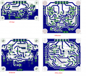
I have 4 IPS boards so far:
- CFP-Mad (6 transistor CFP singleton input)
- VSHA_Classic (Very basic hybrid)
- Cliffjumper (simple 2x LTP input + OS fancy super-duper VAS 😛)
- A9 Ratchet (apex A9 based on IPS with minor changes)
I am on my holidays right now, but try to do some documentation and post it.
THX !!
thimios
The hybrid IPS will work with +/-50V supply, You may have to adjust the trimmer a bit or change two 22k resistors in LTP (anode ones) to 15kR and that is it.
You are so quick !! WOW
The emiter resistors 0,68R you can use even 3 per OP transistor if U would like, there is third hole on the board. Soldering jig is briliant idea !!
I have 4 IPS boards so far:
- CFP-Mad (6 transistor CFP singleton input)
- VSHA_Classic (Very basic hybrid)
- Cliffjumper (simple 2x LTP input + OS fancy super-duper VAS 😛)
- A9 Ratchet (apex A9 based on IPS with minor changes)
I am on my holidays right now, but try to do some documentation and post it.
THX !!
thimios
The hybrid IPS will work with +/-50V supply, You may have to adjust the trimmer a bit or change two 22k resistors in LTP (anode ones) to 15kR and that is it.
Hi borys,
Yes I know I can add a third emitter resistor but do you think it will not work with 0R33 instead of 0R22? I have it finished and will test in the morning. I can't tell from your pics. Do you have a resistor in parallel with the inductor?
I am interested in your IPS designs. Enjoy your vacation. Just show us when your done.
Blessings, Terry
Oh that is good news!Terry
You are so quick !! WOW
The emiter resistors 0,68R you can use even 3 per OP transistor if U would like, there is third hole on the board. Soldering jig is briliant idea !!
I have 4 IPS boards so far:
- CFP-Mad (6 transistor CFP singleton input)
- VSHA_Classic (Very basic hybrid)
- Cliffjumper (simple 2x LTP input + OS fancy super-duper VAS 😛)
- A9 Ratchet (apex A9 based on IPS with minor changes)
I am on my holidays right now, but try to do some documentation and post it.
THX !!
thimios
The hybrid IPS will work with +/-50V supply, You may have to adjust the trimmer a bit or change two 22k resistors in LTP (anode ones) to 15kR and that is it.
Thanks borys🙂
Terry
The resistor is inside the inductor 10R 2W or 3W. Leave for now emiter resistors 0,33, should be fine.
I will put all IPS files at one go in few days but I would like OS to take closer look at them just to check if all looks fine, I have tested them in real life and they are working OK.
Regards Peter
Bellow 3 IPS boards --> files for thermotransfer, the 4th one Ill check after my holidays.
There is still some work left on all of them but they are safe to solder anyway.
IMPORTANT --> tube IPS is causing full DC at the output of the amp before cathodes are heated up so it can be used only with DC protection circuit (it needs approx 5-8s before NFB starts to correct DC).
The CFP-Mad, was tested on +/-45V psu so far.
Attachments
Well testing didn't go as well as hoped. It looked good at first. I played music through it using a Krypton C IPS and all seemed fine. The bias is near the end of adjustment so it looks like it can handle a hot VAS. I then tried the CF-FET through it and it looked fine through my Variac. But then I hooked it up to my A/B setup and it seemed fine still until I turned up the input and then R17-20 caught fire. I wasn't looking at the bias at the moment so I don't know if it shot up but now one of my boards is really ugly. Enough for today.
- Home
- Amplifiers
- Solid State
- SlewMaster Builds