"Front end" is the part that comes before the "Back end." 😉
Usually means a gain stage, such as buffer + autoformer or discrete transistor based small signal amp, or even just an opamp configured to provide some gain.
Thanks! I asked about it before with regards på the V-Fet pt. 2, but everyone thought I was joking. 😛
usually Output Stage is pretty distinctive thing
practically - then everything else (in front of it) is Front End
sometimes OS biasing mechanismus is "part of" OS, sometimes "part of" FE
example - latest Papa's Stasis FE concoction is having biasing mech. for OS as integral part
practically - then everything else (in front of it) is Front End
sometimes OS biasing mechanismus is "part of" OS, sometimes "part of" FE
example - latest Papa's Stasis FE concoction is having biasing mech. for OS as integral part
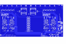
Sissy R.3 rail voltage & parallel mosfets
Hi Zen.
What if increasing rails to 32V and using 2 pairs of mosfets for higher power. Nmos Fqa28n15, Pmos Fqa36p15.
Thnx, stay safe...
rails 23V-sh
Iq 1A7-ish
so, Pheat= (2 x 23Vdc) x 1A7 = 78.2W ~ 80W , per channel
Modushop 4U/400 is, as I'm always saying, Swiss Knife solution
Hi Zen.
What if increasing rails to 32V and using 2 pairs of mosfets for higher power. Nmos Fqa28n15, Pmos Fqa36p15.
Thnx, stay safe...
Biasing scheme
I am currently using Allison type biasing mech. But it operates only in class-A, then heavily distorts. As to your previous measurements opto biasing mech allows higher current ti the load. Bias sliding or leaving class-A nicely ?
Thnx, stay safe.
I am currently using Allison type biasing mech. But it operates only in class-A, then heavily distorts. As to your previous measurements opto biasing mech allows higher current ti the load. Bias sliding or leaving class-A nicely ?
Thnx, stay safe.
Hi Zen.
What if increasing rails to 32V and using 2 pairs of mosfets for higher power. Nmos Fqa28n15, Pmos Fqa36p15.
Thnx, stay safe...
yes, of course, but this thread is about Sissy and you did mention both mosfets 🙂
so, another thred - Babelfish M25 maybe
I am currently using Allison type biasing mech. But it operates only in class-A, then heavily distorts. As to your previous measurements opto biasing mech allows higher current ti the load. Bias sliding or leaving class-A nicely ?
Thnx, stay safe.
of course that every biasing mech. is sliding up to some measure, but here it is not so much of a problem
and, when having OS parts in pure square law arrangement, A Class envelope is stratospheric
OK, DEF is - we know - specific case (I called inverted A Class) where two output parts are working against each other and speaker is getting difference of their current
shown at first in post #195 of Most Greedy Boy, of them all... or (there is no) DEFiSIT of Papa's Koans
anyway, after few years, I finally found biasing solution for this sort of amps, that I'm content with, and even another iteration , used in Babelfish XA252; that one being even better than this one, used in SissySit R.3 and cousins
"Front end" is the part that comes before the "Back end." 😉
Usually means a gain stage, such as buffer + autoformer or discrete transistor based small signal amp, or even just an opamp configured to provide some gain.
Sadly not with my lottery V-fey amps. Need to build more preamps. :S
Some data .... and adequate preamp for SissySIT
Our friend fffO asked me some questions in PM, I'm typing it here, to avoid at least some future repetitive work; his asking in Italic, rest is my reply
for start - some data:
CONTINUOUS POWER OUTPUT (Can you teach me how to calculate?)
8 Ohms; RMS: 18w at 1.55% THD, 20Hz – 20kHz?
4 Ohms: 30W RMS at 1.58% THD, 20Hz – 20kHz?
pretty much visible from graphs/measurements at first page of this very thread; even if this one is for R.3, graphs are pretty much the same/applicable to all 3 iterations of SissysSIT
one disclaimer - "continuous" is term coined with goal that FiFi Sellers are having one more flashy word....... power needs to be continuous as your music is continuous in energy in time domain - no more no less ....... when DIY amp is in question - make it properly regarding PSU and you're outa of thinking about "continuous"
second disclaimer: your amp, being properly made is certainly measuring even better - my measurements deliberately being made with amp being on my T-Bed, crummy PSU common for both channels
FREQUENCY RESPONSE
<10Hz – >20kHz +/-2.5dB
same graphs, second disclaimer
S/N RATIO (REF 1W INTO 8 OHM)
>? dB
same graphs, second disclaimer
CROSSTALK @ 1KHZ
< - ? dB (Dual mono PSU, 2 Tx)
dual mono - hardly any crosstalk
S/N RATIO (REF FULL POWER)
> ? dB
same graphs, second disclaimer
INPUT IMPEDANCES
Input (unbalanced) 99k Ohm
pretty much value of R102 , first post in this thread
POWER CONSUMPTION
400W
per channel - sum of both rails (DC) multiplied with your Iq , add 10% on that for losses, double to get both channels sum
my advice is that you decrease Iq slightly - to 1A8, thinking about dissipation of P channel mosfet - that one is needing care, SIT is not even having slight sweat
GAIN
4X, 12 DB ?
entire gain being job of regular Repeater xformer, connected as Autoformer
that one having 4 identical sections; input signal connected to section 1 ( other end of same being grounded) then we have sections 2, 3, 4 stacked on top of section 1, and output taken from top of section 4
that means that we have original input signal across one section , then same signal stacked trice more, ending with (1+3)=4x of original signal ..........
that means aroundish 12db, smidge less, because World is not ideal and there are always some losses elsewhere in amp , but we are close to that
INPUT SENSITIVITY
Input (unbalanced) ? V RMS
now - let's call declared 18W of output power - 20W for sake of this calculus
20W@8R calls for 35V8pp sine on amp output
if we divide that with our amp's voltage gain (4V/V) , it seems that we need input signal of (35.8Vpp/4)=8V944pp
divide with 1.41, then divide with 2, you get Vrms, so that's 3.16Vrms, as needed signal to put SissySIT to full blast
nowadays sources are almost all having something as 2Vrms on output, so calculus is simple - divide 3.16Vrms with 2Vrms , you get that absolute minimal needed gain of your preamp is going to be 1.581V/V , (log that. multiply with 20) which is 3.98db
now , final part of fffO question - which preamp is adequate?
speaking strictly of gain - any decent preamp with 6 to 9db of gain will do the job; low or moderate Routput, taking in account Sissy Rin of 100K
now, speaking of quality ......... as always my personal opinion and stance (and we all know that ZM's opinions and stances are Absolute Truth):
any preamp having resistive volume attenuator is outa question
best preamp for me is Iron Pumpkin; if that is expensive to you, and I wrote recipe several times here and there - take dual rails B1 buffer and feed it to Slagle (Intact Audio) 200$ (for stereo pair) AVC jobbies; ask and I'll tell how to wire it to have gain ( if needed)
if you're willing - wait to Iron Pre flash in Store and use that , as very good B1 iteration, and use said AVC in place of output autoformer (that not being applicable for Iron Pre balanced, "just" for SE)
Last edited:

any preamp having resistive volume attenuator is outa question
Oh dear! I'm building a switched attenuator for my SissySIT so I will have to sit on the nauti step...

they're good enough if you don't have better
even Mighty ZM will have something form his Kitchen Table, having resistive attenuator ....... for those beancounting heavy-azz Greedy Boyz (meanz - needing fancy remote to govern their Audio Central)

even Mighty ZM will have something form his Kitchen Table, having resistive attenuator ....... for those beancounting heavy-azz Greedy Boyz (meanz - needing fancy remote to govern their Audio Central)
Attachments
Last edited:
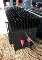
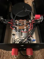
SS rework..
...continued from #529.. Show and tell.. Only a couple of hours playing time for the pair. New car smell too strong right now for proper review. But initial impression is very good. Typical "blanket removed" sort of improvement when you upgrade to better quality parts in mission critical areas. Stock amp maybe 8.9 out of 10, now 9.2 with well recorded acoustic source material. Maybe not so noticeable on your favorite Cannibal Corpse track...
No huge rework here. Removed stock C103 and C104. Replaced with VCAP ODAM 1uF bypassed with VCAP CuTF .022 uF after correspondence with Mr. VenHaus, and ZM concerning value itself. 100's of hours pre break-in on these film caps with an Agilent waveform generator, 100Hz-20kHz swept square wave (logarithmic scale), 20V p-p into 700 ohm load. Removed stock C105 and C106. Replaced with a pair of Nichicon KZ 1000 uF / 50V 'lytics in parallel. Replaced ferromagnetic hardware with non, ferro binding post delete. Mounted industrial isolators with quality tinned-copper ring terminals on amp and speaker leads, brass 1/4-20 bolts. Duelund tinned-copper DCA12GA inside and out. KLE Harmony RCA connections. LED power on relocate. XT60 connectors for the rail supply (my weird "ship in a bottle" amp configuration is hard to work with). Two switches there are for manual soft start, already had that though.
Attachments

- Home
- Amplifiers
- Pass Labs
- SissySIT R.3