No Sound from my new SissySit3
I am working on my SissySit R.3 and have a problem common to both channels.
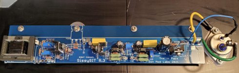
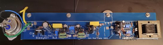
Using ZM's boards, standard dual mono power supply with 22v5 rails, all parts from reputable sources, including the THF-51s SITs. All parts checked for correct value / function prior to assembly. I even checked zener voltages and BD139/140s on an Atlas DCA75 Pro transistor checker.
I am using the Edcor PC 600/600 autoformers.
The boards went together without a problem and have biased up without a hiccup. 1A7 per channel, 200mv Iq on the buffer, stable zeroed offset on the buffer and outputs.
My problem is no signal making it to the outputs.
I attached the amp to speakers, no hum or buzz noted. But no sound output.
I went back to dummy loads and injected a 1v 1000hz signal and get 1v0 at the jumper, stepped up voltage, I think about 2v at pin 6 of the edcor, but from pin 5 all the way to the outputs, no AC voltage noted at the jumped R111 spot, or gate and source of the THF. The signal is a clean sine wave up to Pin 5, then nothing.
I checked the windings and all are OK, and reflowed the Edcor solder joints, no change noted. They are mounted in correct orientation on the boards.
All component orientations were rechecked, no shorts noted after 4x checking the top and bottom of boards.
These other voltages are noted. R L
VDC across level shifter 120R 3v555 3v531
SIT G/S DC voltage 3.702 3.690
IRFP9140 G/S volts DC 3.860 3.851
I am not sure what to do next.....
Any suggestions on what to test/replace next would be greatly appreciated.
Matt
I am working on my SissySit R.3 and have a problem common to both channels.
Using ZM's boards, standard dual mono power supply with 22v5 rails, all parts from reputable sources, including the THF-51s SITs. All parts checked for correct value / function prior to assembly. I even checked zener voltages and BD139/140s on an Atlas DCA75 Pro transistor checker.
I am using the Edcor PC 600/600 autoformers.
The boards went together without a problem and have biased up without a hiccup. 1A7 per channel, 200mv Iq on the buffer, stable zeroed offset on the buffer and outputs.
My problem is no signal making it to the outputs.
I attached the amp to speakers, no hum or buzz noted. But no sound output.
I went back to dummy loads and injected a 1v 1000hz signal and get 1v0 at the jumper, stepped up voltage, I think about 2v at pin 6 of the edcor, but from pin 5 all the way to the outputs, no AC voltage noted at the jumped R111 spot, or gate and source of the THF. The signal is a clean sine wave up to Pin 5, then nothing.
I checked the windings and all are OK, and reflowed the Edcor solder joints, no change noted. They are mounted in correct orientation on the boards.
All component orientations were rechecked, no shorts noted after 4x checking the top and bottom of boards.
These other voltages are noted. R L
VDC across level shifter 120R 3v555 3v531
SIT G/S DC voltage 3.702 3.690
IRFP9140 G/S volts DC 3.860 3.851
I am not sure what to do next.....
Any suggestions on what to test/replace next would be greatly appreciated.
Matt
Attachments
Problem is known - we already solved it in one of threads with construction using those 3 xformers (combined/per choice)
can't remember was it Iron Pre or some of other amps having same FE as SissySIT
reason - Edcor 600:600 having mislabeled/wrong pinout in their Datasheet
will prepare graphical how-to for you tomorrow, now too sleepy
of course that , as soon I got to that omission, I did corrected it in pcb files, but evidently after you got your set
edit: I did check pcbs with Cinemag and with Jensens (which I both have) but didn't had Edcor 600:600 on hand, so I logically trusted in their datasheet
Last edited:
I didn't made (probably my mistake) big fuss of it, simply because majority of Guyz are mounting Cinemags
other reason (certainly not excuse) is that I'm .......... well - all over several amp threads, sometimes loosing where I wrote what

other reason (certainly not excuse) is that I'm .......... well - all over several amp threads, sometimes loosing where I wrote what
well, for tonight "just" this :
you need first to isolate, then reverse connection of Edcor pins 5 and 7
trouble is - if you want to do that on pcb, you must to desolder them out of pcb, to have approach to upper copper traces
easy way of doing that is with desoldering station (sucking de-solder gun); any other way is more tedious and tricky - using manual solder sucker is not so effective and you need to take care of temperature, or xformer pins are going outa plastic bobin
other way - already done by one clever Greedy Boy - he made operation on Edcor itself - carefully desoldered wires from pins 5 and 7, and re-soldered it opposite (using some thin wire as extension)
if you need graphic how to for pcb salvage, buzzz and I'll post it tomorrow
I would like to change the wiring on the Edcor, I think I have the right gauge wire here, but please show me you recommended pcb salvage technique so I can directly compare before I proceed, thanks for all ZM!
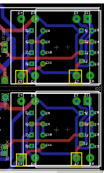
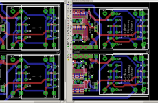
now , without any markings, to enable clear view of traces;
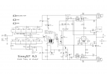
left is - as is - Edcors bad, right is as I edited pcbs later
goal is to cut all traces (both bottom and top ones) connected to pins 5 and 7, then using xacto knife for scraping ends of cut traces, using thin wire and soldering them adequately, to establish proper connection of windings
schematic with proper Edcor pinout marked also enclosed
in the end, prior to powering it On, check is simple, resistance measurement :
- Edcor pin 2 to GND (or jumper - pin X to GND) - reads XX Ohms
-R111(211) to GND - reads 4*(XX) Ohms
where XX is practically Rdc of one (of four) Edcor winding sections
if you need more help about cutting and connecting, say
Attachments
Phew!
Thanks Oh Mighty One. I have the 'bad' PCBs but fortunately I'm using Cinemag so at least I don't have to worry about this.
Thanks Oh Mighty One. I have the 'bad' PCBs but fortunately I'm using Cinemag so at least I don't have to worry about this.

...continued from #529..
Removed stock C103 and C104. Replaced with VCAP ODAM 1uF bypassed with VCAP CuTF .022 uF after correspondence with Mr. VenHaus, and ZM concerning value itself. ...
Removed stock C105 and C106. Replaced with a pair of Nichicon KZ 1000 uF / 50V 'lytics in parallel.
If I got it right, you removed C104 (22uF Elna Silmic II) and C103 (1uF MKC bypass), replacing them with a single 1uF ODAM cap (bypassed with 0.022uF CUTF). You also removed C106 (3300uF) replacing it with two paralled 1000uF (Nichicon KZ) and discarded C105 (1uF MKC bypass).
I think I understand what you were trying to achieve, but I have the following doubts:
Both modifications involved a loss of capacitance. Do they bear any noteworthy implications for the operation of the amplifier circuit? And if so, did you perform any other "corrective" adjustments to the circuit? Or are these modifications completely harmless?
@ZM
Please feel free to intervene. 🙂
Thanks.
well, I didn't understood that sole Silmic is removed (maybe didn't read carefully)
in that case, low freq. are compromised
Silmic position is seeing something as 20K-22K ..... which is Rin of OS with biasing mech.
in that case, low freq. are compromised
Silmic position is seeing something as 20K-22K ..... which is Rin of OS with biasing mech.

yup, you got it
Beauty of Audiophoolery ......... I did it all, not just once
result, with 1u1 there, bass Freq. are being compromised starting from 20Hz down
not overly critical, but I don't like phase twisting resulting from that
Beauty of Audiophoolery ......... I did it all, not just once
result, with 1u1 there, bass Freq. are being compromised starting from 20Hz down
not overly critical, but I don't like phase twisting resulting from that
I use SissySIT for everything above 80 Hz in my setup. A Rythmik E15HP2 servo sub takes care of everything below 80 Hz. Beauty of DIY, things can be "customized" for your own particular situation and interest. Sorry for not providing valuable information with my show and tell.
Thank you for taking the time to explain your particular situation.
Not being as wise as ZM, I can appreciate the pleasures of Audiophoolery. 😀
I was really captivated by your mods and intrigued with the idea of replicating them on my amp. However, being a novice, I wasn't sure about that. From yours and ZM's replys, I deduce that in my particular case it is not advisable.
Thanks again.
in this case, William did show that his Audiophoolery days are long gone .....
me... I still have few ideas to try
me... I still have few ideas to try
A quick update on my SissySit R.3 build.
I changed the transformer winding ends between pin 5 and 7 on my Edcor 600:600 transformers and all seems well now.
First impressions are as positive as most others on this thread have noted.
I will give the amp a couple weeks of play and then get my impressions and a few pics up, even though my build is a typical 4U/400 dual mono Pass type build.
Thanks again ZM, and thanks to Mr. Pass for starting all of this!!

- Home
- Amplifiers
- Pass Labs
- SissySIT R.3