Post #480 wasn't the end of the story ...
Well, in post #480 I reported that in my SissySIT R.3 build, the offset seemed stable after changing the level shifter resistor on the left side so that there is about equal Ugs of 9140 compared to "voltage between gate of IRF510 and output". The latter consists of Ugs of IRF510 plus the voltage over the level shifter resistor, minus Ugs of SIT.
Unfortunately, that still didn't cure the issue of high and unstable offset after warm-up.🙁
So, soon after posting #480 I took the left side board off the heatsink again and changed the offset trimmer and Q103. In addition, I reflowed every solder joint that I thought of having some connection with determining offset.
Much better after that, but a bit of offset shift was still there. That went away after changing the optos back to the old ones (same as on the right side).🙂
I did monitor offset and bias for about a week after that, and found no instability and offset runaway anymore. About a week ago, I bolted down the top and declared my SissySIT R.3 done. And it sure sounds better when you're not constantly looking at offset meters while listening ... 😀
Just for reference, maybe interesting for other builders:
In my amp, I have rail voltage fluctuations caused by variation in wall AC voltage. Over the course of a day, typically between 220V to 230V AC.
On the right side, the level shifter resistor compensates only for Ugs of SIT. Here, after the amp is fully warmed up, offset varies with rail voltage fluctuations by less than 5 mV.
On the left side, where the level shifter is chosen to provide equal "Ugs" voltage between up and down side, offset varies by approx. 25 mV.
Of course, this could be due to my individual combinations of SIT and MOSFET Ugs (and I'm reluctant to open the amp again and change the level shifter on the left side 😛).
I suggest that you try both approaches and see which one works best in your case.
Anyway, I'm happy with this amp now, stable and quiet, and am just listening.
On the building side of things, now adding filters to my Sony VFET, and in the process of stuffing Marauder cards ... 😉
Regards, Claas
Class,
Thanks for getting back to us, I have been paying attention to your trials. Glad you got it stabilized and enjoying your amp. It inspires me to keep chugging along with mine. ZM it is nice to see you build complete amps, I am sure it has to be rewarding getting a chance to stop and enjoy the the music.
Bill
Last edited:
tnx ww
I've just posted few more pics over in LuDEF thread
music - I'm listening to music all my awake time ; wrote already somewhere - I would listen the music 24h but Boss did forbid music in bedroom while sleeping
ZM obeys, what else ....... even ZM is having a Boss ( living with all sorts of females, so pretty much obeys them all)
🙂
You could do like I did and put headphones in the bedroom. My wife retired from grooming dogs for 45 years and she still loves dogs. It is good to see you have passion for you work. One of my Aleph 30s I used a inductor in the power supply it ran almost ran as hot as the heat sinks.
Bill
Bill
Last edited:
chokes - these are custom made for exact duty, cold as ......... environment 🙂
don't like cans, I'm using them very rarely, even if - as any hoarder around, have nice stash of decent ones and handy ones
frankly, most cherished ones are JBL Synchros E50 BT - handy ........ in fact necessary , when flying to visit Pa, and back
even forgot first ones at SR, bought some drek on SF airport and as soon I got back, bought 2 SH ; first thing was to glue them (hate folding function) also preserving inner cabling from going south
K270 Studio still being best I have ....... and frankly - who needs better, just to keep them in fabric bag
Last edited:
A little more progress today. I completed the power supplies with the installation of one of Mark Johnson's soft start-up boards.
Now on to the amp board installation.


Now on to the amp board installation.

A while back I posted about inserting a passive attenuator right in front of the SissySIT buffer and I now have to assemble the attenuator ready for installation - the overall project is progressing well and I'm now close to installing the SissySIT board and hooking it up.
Just to be clear, my SissySIT will be used with a single source so the attenuator will be in the SissySIT chassis just a few centimetres from the PCB inputs. I plan to use a shunt attenuator. I will, at various times, plug in different source components but none of them are problematic in terms of having unusually high output impedances, though some are only around 600mV output.
Anyway, I'm seeking advice on the optimal configuration of the attenuator with respect to the buffer input, specifically R101 and R102 (referenced to the schematic in ZM's post #1). Should I just connect the output of the attenuator to the SissySIT input (R101) or should I replace R101 and R102 with the attenuator, or maybe something else? I have to calculate and order the resistors for the attenuator so I can adapt the shunt resistor to an appropriate value, typically between 10K and 100K.
Thanks for your indulgence.
change Rin of Sissy to your liking, so it will serve as final shunting resistor for your attenuatorA while back I posted about inserting a passive attenuator right in front of the SissySIT buffer and I now have to assemble the attenuator ready for installation - the overall project is progressing well and I'm now close to installing the SissySIT board and hooking it up.
Just to be clear, my SissySIT will be used with a single source so the attenuator will be in the SissySIT chassis just a few centimetres from the PCB inputs. I plan to use a shunt attenuator. I will, at various times, plug in different source components but none of them are problematic in terms of having unusually high output impedances, though some are only around 600mV output.
Anyway, I'm seeking advice on the optimal configuration of the attenuator with respect to the buffer input, specifically R101 and R102 (referenced to the schematic in ZM's post #1). Should I just connect the output of the attenuator to the SissySIT input (R101) or should I replace R101 and R102 with the attenuator, or maybe something else? I have to calculate and order the resistors for the attenuator so I can adapt the shunt resistor to an appropriate value, typically between 10K and 100K.
Thanks for your indulgence.
So front end is another name for buffer?
SissySIT has a buffer in front of the the autoformer.
"Front end" is the part that comes before the "Back end." 😉
Usually means a gain stage, such as buffer + autoformer or discrete transistor based small signal amp, or even just an opamp configured to provide some gain.
Usually means a gain stage, such as buffer + autoformer or discrete transistor based small signal amp, or even just an opamp configured to provide some gain.
change Rin of Sissy to your liking, so it will serve as final shunting resistor for your attenuator
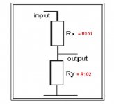
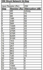
Thanks mighty ZM, just to confirm the understanding of a simple mortal is my diagram below correct? If so, for a 25K0 shunt attenuator, R101 will be 25K0 and R102 will vary between 0R0 and infinity, as per the second attachment.
Attachments
yup, like that
though most convenient way to do that, change onboard shunt resistor (R102) to 1Meg, so you can freely ignore Sissy as loading element (while still having 100R in place, serving as gate stopper resistor)
then assemble your attenuator as usual and that's it
though most convenient way to do that, change onboard shunt resistor (R102) to 1Meg, so you can freely ignore Sissy as loading element (while still having 100R in place, serving as gate stopper resistor)
then assemble your attenuator as usual and that's it
Last edited:
- Home
- Amplifiers
- Pass Labs
- SissySIT R.3