Hi 4pyros,
I'm with djk, but a 1000 Ohm resistor is large enough. Then you can use the precision 10 Ohm resistor in place of the speaker for an initial calibration. If any of this is unclear, get a WT3 🙂.
Regards,
I actually prefer using a much smaller high-power resistor (e.g. 4 ohms) and using the method I suggested. It's a longer approach, but it also allows me to generate much higher voltages across the speaker and therefore track how t/s params might shift under higher drive levels.
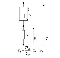
Yes you are right Brian, for accurate measurements your should change the 10 Ohm resistor in at least half the Re of the loudspeaker. You also need to measure the resistance of the cables.
Last edited:
"I'm with djk, but a 1000 Ohm resistor is large enough."
No, it's not.
Some low Qes drivers can have impedance peaks in excess of 200Ω. A 1000Ω resistor in series with that kind of driver is hardly constant current, and will result in inaccurate parameters.
I generally use a Crest amplifier that will drive 92V RMS.
No, it's not.
Some low Qes drivers can have impedance peaks in excess of 200Ω. A 1000Ω resistor in series with that kind of driver is hardly constant current, and will result in inaccurate parameters.
I generally use a Crest amplifier that will drive 92V RMS.
Last edited:
Post #864
Hi djk,
It's probably mostly irrelevant to the discussion of the SS15, but 1000 Ohm is quite a normal value for this measurement. I have never heared of anybody that applies 92Vac to the constant current circuit for measuring loudspeaker impedance, but that just proves, that I have to get out more. 🙂
Regards.
I realize that that is the value that most people use, and I explained why it is an incorrect choice.
BTW, my HP 200 generator (tubes) can put out 40V into 600Ω.
BTW, my HP 200 generator (tubes) can put out 40V into 600Ω.
back to ss15 projects 😛😀
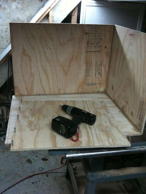
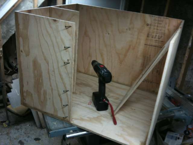
here i just started today, didn't order the 3015 yet, will do that this week. going to dinner now will continue construction later on tonight!
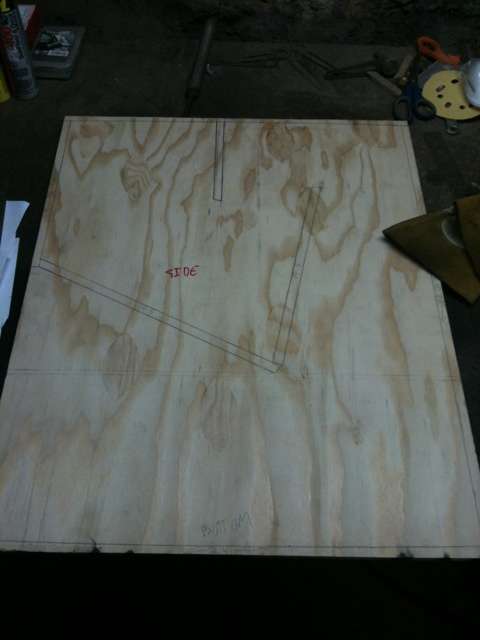
good ol made in USA ply
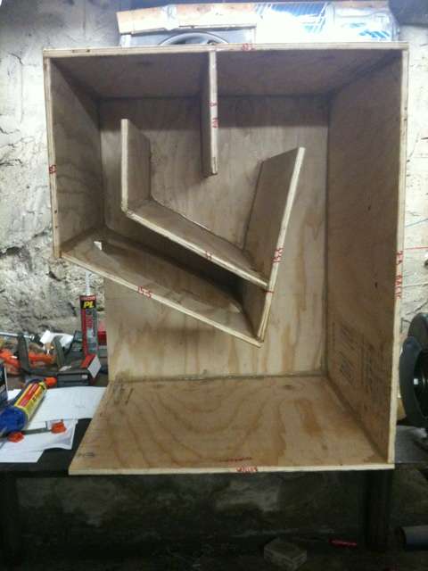
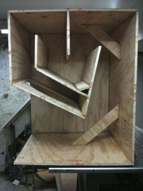
got everything cut, started tracing out on the side piece. i also added some angled cuts to the pieces that don't meet at 90 deg to make it go together a little better.
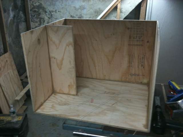
should i add corner reflectors in every corner? i don't mind the small amount of extra added weight if they'll help and i have the wood sitting here....
here i just started today, didn't order the 3015 yet, will do that this week. going to dinner now will continue construction later on tonight!
good ol made in USA ply
An externally hosted image should be here but it was not working when we last tested it.
got everything cut, started tracing out on the side piece. i also added some angled cuts to the pieces that don't meet at 90 deg to make it go together a little better.
should i add corner reflectors in every corner? i don't mind the small amount of extra added weight if they'll help and i have the wood sitting here....
I have a Mac so I can't as far as I know 🙁 unless hornsresp works on a Mac now ? (not running windows on a Mac)
And woopss I meant 4pi Aka Into free space (that's how I'll be using my ss15)
Hi, FYI hornresp works fine on Intel Macs under "WineBottler" (windows emulator)
Give it a search, just my 2 pence.
Al
I only used corner reflectors to rid the box of parallel sides in the wave path. Look at pic in post #827. I only needed 3 at 15 degrees each. Andyshould i add corner reflectors in every corner? i don't mind the small amount of extra added weight if they'll help and i have the wood sitting here....
Its bigger and made out of 3/4 ply. You have seen my posts? AndyAndy, is your cab an 'original' SS15 or did you change it a little?
Yes, but I couldn't find a detailed drawing and I wasn't sure you kept yourself to that extension idea.
Here are the unofficial results. I wish it was better down lower but I got a good peak at 180Hz. I am calling it good to make more. Any other thoughts? Andy
Congrats: you made it over the finish line !! AND... you made it your own.
I'm congratulating you on your learning, your design efforts, and your follow through to a finished product.
Now, compare your results to a 'gold standard' http://www.danleysoundlabs.com/pdf/old/Danley TH-115 Spec Sheet.pdf and you'll realize how close to gold you got... Yea the gold standard has 40hz above and beyond what a ss15 (and your variant) has... that's to be expected. You are not an industry leading speaker designer.
But for a $250 sub? (assuming you have $100 in baltic per) Holy cow that is close !!
Yea I want more 40hz from the ss15 too, and have agonized over it. In the end -- the agony is probably just not worth it. Getting this close for a DIY effort is in my mind a real feat, and you should be congratulated for getting there.
(now, how much does it weigh????) 😉
Now, compare your results to a 'gold standard' http://www.danleysoundlabs.com/pdf/old/Danley TH-115 Spec Sheet.pdf and you'll realize how close to gold you got... Yea the gold standard has 40hz above and beyond what a ss15 (and your variant) has... that's to be expected. You are not an industry leading speaker designer.
Hmm... 40 Hz should be possible. There are some clues in the impedance plot for the TH-115 that suggest how it can be accomplished (basically aiming for a longer path length that results in a lower resonant point of 35 Hz, then fixing the upper part of the passband (~140 Hz?) with some sort of resonator (or "dogfood duct", LOL).
An impedance plot of the SS15 would go a long way in helping to determine how much it differs from the TH115.
You probably won't be able to do all of this with one sheet of ply though 🙂
Here is the final result before the start of the night.
Did a quick check at opposite end of room which read just over 115 DB. Room width is 112 feet. Setup is 15 feet off rear wall. Wasn't a sine wave. Was using Moby's GO 2006 remix.
It definitely fed my addiction for a bit.
An externally hosted image should be here but it was not working when we last tested it.
Did a quick check at opposite end of room which read just over 115 DB. Room width is 112 feet. Setup is 15 feet off rear wall. Wasn't a sine wave. Was using Moby's GO 2006 remix.
It definitely fed my addiction for a bit.
man that looks sweet. 😀 with subs split at that distance you must have been in power alley territory though. did you think about other stacking arrangements?
ps. i looooove trussing... 😱
ps. i looooove trussing... 😱
Here is the final result before the start of the night.
An externally hosted image should be here but it was not working when we last tested it.
Did a quick check at opposite end of room which read just over 115 DB. Room width is 112 feet. Setup is 15 feet off rear wall. Wasn't a sine wave. Was using Moby's GO 2006 remix.
It definitely fed my addiction for a bit.
Are these also custom / DIY tops?
Regards, Ben
I still need to weigh it. I will get back to you.(now, how much does it weigh????)
Would it make any sense to measure my boxs at 28.3VRMS @10 Meters like Danley dose? Then may be my tests would be more concusive. Andy
- Home
- Loudspeakers
- Subwoofers
- Single sheet TH challenge