An overview of SS15 with old and new 3015lf driver and the SS15 with 18Sound 15W700.
Hey I just noticed those were all 2 pi tests. Do you have those comparisons with 1 pi testing?
And if I'm reading it correctly, those sims are at 2.83V right?
Last edited:
Just download HornResp and you can copy the numbers as given in my examples for the drivers you like to see (halving Pi means +5dB)
The maximum safe excursion and SPL graphs are calculated for each driver independently. In these graphs you can find the corresponding power in Watts and excursion in millimetres. In reality the excursion will be less then predicted since HornResp isn't able to predict the compression factor for each driver.
The maximum safe excursion and SPL graphs are calculated for each driver independently. In these graphs you can find the corresponding power in Watts and excursion in millimetres. In reality the excursion will be less then predicted since HornResp isn't able to predict the compression factor for each driver.
I have a Mac so I can't as far as I know 🙁 unless hornsresp works on a Mac now ? (not running windows on a Mac)
And woopss I meant 4pi Aka Into free space (that's how I'll be using my ss15)
And woopss I meant 4pi Aka Into free space (that's how I'll be using my ss15)
Last edited:
4 pi works the other way around so -5dB will work. Any drivers in particularly you are interested?
Finally had a chance to do a bit of testing outside. I also tried to put to numbers some of the things I knew, but never documented. (like on side vs upright)
I also did a quick 'directivity test' where I drew a 10meter circle, started a sine wave and then walked around with a spl meter.
Pretty interesting stuff (at least to me....)
I also did a quick 'directivity test' where I drew a 10meter circle, started a sine wave and then walked around with a spl meter.
Pretty interesting stuff (at least to me....)
Attachments
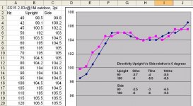
Nice results Jbell. But before you make a conclusion between horizontal and vertical position, remember that you are measuring trough a tiny microphone membrane and nobody puts his ear to the ground (not meant as critic but as a reminder ;-).
Last edited:
Finally had a chance to do a bit of testing outside. I also tried to put to numbers some of the things I knew, but never documented. (like on side vs upright)
I also did a quick 'directivity test' where I drew a 10meter circle, started a sine wave and then walked around with a spl meter.
Pretty interesting stuff (at least to me....)
Distant surroundings can have significant impact on LF test results, as I found with my outdoor directivity tests.
What was the distance between the SS15 and the nearest building ?
What was the direction of the SS15 in relation to the nearest building?
Art
Jim; I would like to do my testing as close to yours as posible. Did you set your level to 2.83VRMS using 60Hz? AndyPretty interesting stuff (at least to me....)
Jim; I would like to do my testing as close to yours as posible. Did you set your level to 2.83VRMS using 60Hz? Andy
When I do my sine wave tests, I just leave the meter connected. If there is a bit of drift off of 2.83v, I make fine adjustments.
Can I cheak the resonance of the TH sub by cheaking the AC current with a DVM and looking for a Dip? Andy
Can I cheak the resonance of the TH sub by cheaking the AC current with a DVM and looking for a Dip? Andy
Suggestion: Get a WT3 and use it to measure the impedance response of the TH. It will tell you all you need to know, including the resonance points, AND if there are any sections that need more bracing.
Ya I dont think I want to go that far to test one speaker, maybe I would measure the voltage across a resistor if I had to. AndySuggestion: Get a WT3
Ya I dont think I want to go that far to test one speaker, maybe I would measure the voltage across a resistor if I had to. Andy
Believe me, once you starting building speakers, a WT3 is probably one of the best, if not THE best tool you can have in your toolkit.
You can take the long way around and hook a resistor in series with the speaker, and then use voltage measurements across that to calculate impedance at varying frequencies. A WT3 will do the same for you in seconds. It's worth the $$.
I believe you, But I am only making one speaker.Believe me, once you starting building speakers, a WT3 is probably one of the best
Cant I do the same thing by measuring the AC current with a DVM?You can take the long way around and hook a resistor in series with the speaker, and then use voltage measurements across that to calculate impedance at varying frequencies.
Andy
I believe you, But I am only making one speaker.
Cant I do the same thing by measuring the AC current with a DVM?
Andy
Sure, if your DVM has an internal impedance of zero and it can measure current accurately for frequencies from 0 to 200 Hz or so 🙂.
The woofer tester has an AC constant current source that drives the speaker and an AC voltmeter to measure the resulting voltage drop and then calculates the impedance from this data.
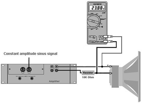
No, put a 10KΩ in series with the driver and measure the voltage across the driver with a true RMS AC voltmeter.
Hi 4pyros,
I'm with djk, but a 1000 Ohm resistor is large enough. Then you can use the precision 10 Ohm resistor in place of the speaker for an initial calibration. If any of this is unclear, get a WT3 🙂.
Regards,
I'm with djk, but a 1000 Ohm resistor is large enough. Then you can use the precision 10 Ohm resistor in place of the speaker for an initial calibration. If any of this is unclear, get a WT3 🙂.
Regards,
Last edited:
- Home
- Loudspeakers
- Subwoofers
- Single sheet TH challenge