What Zen Mod said, no pad needed for puck.
Yes, use existing holes in the heatsink where feasible, and a thin layer of thermal paste between plate and heatsink.
Also nylon shoulder washers at SIT screws.
Yes, use existing holes in the heatsink where feasible, and a thin layer of thermal paste between plate and heatsink.
Also nylon shoulder washers at SIT screws.
As a Mu Follower Follower this amplifier is not pure single ended. The mosfet in the constant current source part of the circuit contributes to the overall power output, in a push-pull sort of way. So the maximum power output at 4 Ohm may be considerably more than half of the maximum power output at 8 Ohm. This is particularly a plus if your speakers' impedance is much lower than 8 Ohm. Since this amplifier has higher output power it may be used with speakers of lesser sensitivity, and many of these speakers' impedance is lower than 8 Ohm. Therefore the 4 Ohm power output of the amplifier is useful information.
When I first built this amplifier I ran it at 2.5A. At 8 Ohm loading the maximum power output was somewhere between 45 and 50W, depending on the maximum amount of distortion that is tolerated.
I tested the amplifier with a 4 Ohm load and clipping started at about 28W. I also simulated the 4 Ohm load condition on LTSpice and the result was quite close to the real thing. So the LTSpice model of this amplifier seemed to give fairly accurate results.
I have been running my amp at 3.0A lately for slightly higher 8 Ohm power output of 50W and lower distortion. I will post the 3.0A 4 Ohm results next.
Here are the results for 2.5A:
LTSpice Simulation:


Actual measurements of right Channel:
Onset of clipping at 28W @ 4 Ohm:


Clipping at 30W @ 4Ohm:


When I first built this amplifier I ran it at 2.5A. At 8 Ohm loading the maximum power output was somewhere between 45 and 50W, depending on the maximum amount of distortion that is tolerated.
I tested the amplifier with a 4 Ohm load and clipping started at about 28W. I also simulated the 4 Ohm load condition on LTSpice and the result was quite close to the real thing. So the LTSpice model of this amplifier seemed to give fairly accurate results.
I have been running my amp at 3.0A lately for slightly higher 8 Ohm power output of 50W and lower distortion. I will post the 3.0A 4 Ohm results next.
Here are the results for 2.5A:
LTSpice Simulation:
Actual measurements of right Channel:
Onset of clipping at 28W @ 4 Ohm:
Clipping at 30W @ 4Ohm:

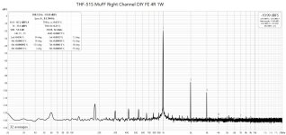
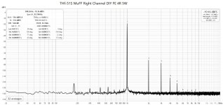
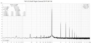
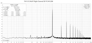
Here are the rest of the 2.5A 4 Ohm distortion measurements:
Attachments
And here is the 62VDC 3.0A 4 Ohm clipping LTSpice simulation:


And here are the 4 Ohm measurements of the amplifier at clipping:


Increasing the quiescent current to 3.0A resulted in a big increase in 4 Ohm performance.
The LTSpice simulation results were fairly close to the actual measurements.
And here are the 4 Ohm measurements of the amplifier at clipping:
Increasing the quiescent current to 3.0A resulted in a big increase in 4 Ohm performance.
The LTSpice simulation results were fairly close to the actual measurements.
Last edited:
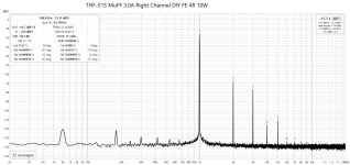
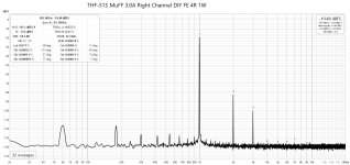
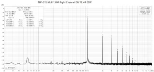
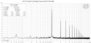
Here are the rest of the 3.0A 4 Ohm distortion measurements:
Attachments
-
 THF-51S MuFF 3.0A Right Channel DIY FE 4R 10W.jpg191.6 KB · Views: 58
 -
 THF-51S MuFF 3.0A Right Channel DIY FE 4R 1W.jpg192 KB · Views: 55
 -
 THF-51S MuFF 3.0A Right Channel DIY FE 4R 20W.jpg191.9 KB · Views: 51
 -
 THF-51S MuFF 3.0A Right Channel DIY FE 4R 30W.jpg192.2 KB · Views: 55
 -
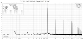 THF-51S MuFF 3.0A Right Channel DIY FE 4R 40W.jpg193.3 KB · Views: 55
I also looked at the 75VDC 3.0A version. The 8 Ohm maximum power was 70W. The 4 Ohm output started clipping at about 54W with 0.69% THD. At 2% THD power output was 60W @ 4 Ohm.
Clipping at 54W @ 4 Ohm:


Clipping at 60W @ 4 Ohm:


Clipping at 54W @ 4 Ohm:
Clipping at 60W @ 4 Ohm:
Last edited:
The rest of the 75VDC 3.0A 4 Ohm distortion measurements:
Attachments
-
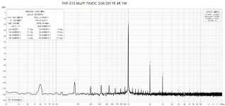 THF-51S MuFF 75VDC 3.0A DIY FE Left Channel 4R 1W.jpg191.3 KB · Views: 64
 -
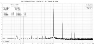 THF-51S MuFF 75VDC 3.0A DIY FE Left Channel 4R 10W.jpg192.9 KB · Views: 63
 -
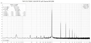 THF-51S MuFF 75VDC 3.0A DIY FE Left Channel 4R 20W.jpg191.6 KB · Views: 63
 -
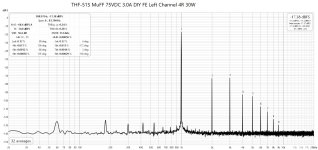 THF-51S MuFF 75VDC 3.0A DIY FE Left Channel 4R 30W.jpg192.9 KB · Views: 63
 -
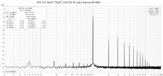 THF-51S MuFF 75VDC 3.0A DIY FE Left Channel 4R 40W.jpg193.9 KB · Views: 63
 -
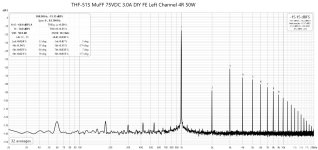 THF-51S MuFF 75VDC 3.0A DIY FE Left Channel 4R 50W.jpg194.7 KB · Views: 65
Ben, I have read this thread and the Sit-3x thread. Great work. I am very appreciative of all the work you have done re SIT followers. Could I please get the Gerbers for the 75-90 volt THF-51s MuFF version.
Thank you, again.
Don
Thank you, again.
Don
Hi Don,
I do not have a 75V - 90V version.
The PCBs that I did will work up to 80V, and that is limited by the size of the capacitors that will fit on the PCBs, although I do not recommend using an 80V power supply. I recommend keeping the power supply to 75V in order to not exceed the specified voltage of the capacitors.
I originally built the amps using a power supply that put out about 63V. I recently changed one channel to a 75V power supply and the circuit changes were shown here:https://www.diyaudio.com/community/...mu-follower-amplifier-45w.371187/post-7867907
The original PCB was used for this change. R4 was no longer required and was replaced with a wire jumper. R7 was changed from one 0.1R to two 0.1R in series. Alternatively R7 and R8 may be changed to 0.15R 5W each.
I do not intend to build a higher version for an even higher voltage power supply as 100V electrolytic capacitors are quite expensive. Furthermore higher voltage means also higher heat dissipation, probably pushing the THF-51S to its practical limit or over its practical limit.
Last edited:
If you have enough heatsinking/cooling, 3A is doable. Right now I have one channel running at 75V and 3A and the other at 63V and 3A. The 75V amp is good for 70W at 8 Ohm and the 63V amp is good for 50W at 8 Ohm.
The heat dissipation is appreciated right now!
The heat dissipation is appreciated right now!
And by the way, because of the contribution of the mosfet in the mu follower circuit, the 4 Ohm power is not bad either.
At 63V and 3A, the power was 42W at 4 Ohm. THD was 0.96%.
At 75V and 3A, the power was 54W at 4r Ohm. THD was 0.69%.
At 63V and 3A, the power was 42W at 4 Ohm. THD was 0.96%.
At 75V and 3A, the power was 54W at 4r Ohm. THD was 0.69%.
Does anybody knows how to get the 3rd and higher harmonic distortion profiles much more down compared to the 2nd harmonic? So that mostly it will be a 2nd harmonic distortion.
Reduce the power output so it's not clipping. Look at the FFTs at lower power output. Or increase the power supply voltage.
I hope that we can do better than just lowering output power. 😆 I am sure that someone knows some tricks for that. 😊Reduce the power output so it's not clipping. Look at the FFTs at lower power output.
When the amp is clipping, there will be lots of harmonics. If you increase the power supply voltage, the amp will be able to output more power before clipping. However, there is the additional heat dissipated by the SIT to be dealt with.
It may also be possible to adjust R2 and R13 to tune the push-pull action which may increase power output, although that will also change the distortion profile.
It may also be possible to adjust R2 and R13 to tune the push-pull action which may increase power output, although that will also change the distortion profile.
Will this work with another SIT too? Just adjustable bias? Or slight adaptation of the trimmer (answer = yes, trimmer is 200K ansd allows a crazy range) to get the Vgs -7V for the likes of 2SK180, or 2SK182? Have them . . .
I don't need the 3Amps/75V (my wife will see the power bill. . .). 40V @ 2Amp is a lot already, enough is enough, because remember, we normals listen only to the first one or five watts. Even on 4Ω.
I saw a layout (ZM??) i remember that has pre-drilled holes for the P-FET 'module', which is handsome.
Note that distortion plot is for 4 Ohm speaker load. The second harmonic is dominant for the full power range into 8 Ohm.
At 4 Ohm, the third harmonic becomes dominant at higher power output. At low power output the second harmonic is dominant.
Decrease the quiescent current will increase the second harmonic but it will also decrease the maximum power output.
Decrease the mosfet's contribution to the power output will increase the second harmonic into 4 Ohm. That will also decrease the maximum 4 Ohm power output.
- Home
- Amplifiers
- Pass Labs
- Single Ended Tokin SIT THF-51S Common Drain Mu Follower Amplifier, 45W?