Hi,
I am trying to figure out the best ground layout for the amp before I solder Front-End wires.
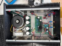
The current idea is to have a star ground at the PSU (picture attached). There is ground connection between PSU and SIT board and PSU and Front-End. No ground connection between the SIT and Front-End board. Would that be the best layout? Or rather go with PSU – SIT – Front-End – XLR ground layout.
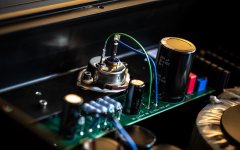
I also noticed that the SIT surface is not 100% flat. The area around mounting holes does not touch the heat-sink perfectly. It seems Mr. Nelson is using some kind of silicone in his SIT-5 (picture attached). Does it make sense to use a silicone grease (link below) or just regular thermal pad is ok?
https://a.co/d/aWDax09
Cheers
I am trying to figure out the best ground layout for the amp before I solder Front-End wires.
The current idea is to have a star ground at the PSU (picture attached). There is ground connection between PSU and SIT board and PSU and Front-End. No ground connection between the SIT and Front-End board. Would that be the best layout? Or rather go with PSU – SIT – Front-End – XLR ground layout.
I also noticed that the SIT surface is not 100% flat. The area around mounting holes does not touch the heat-sink perfectly. It seems Mr. Nelson is using some kind of silicone in his SIT-5 (picture attached). Does it make sense to use a silicone grease (link below) or just regular thermal pad is ok?
https://a.co/d/aWDax09
Cheers
Attachments

Power supply wiring: V- and G wires from power supply board Output to amplifier board V- and G. Twist wires.
For the FE board, it should be configured for V- and G. To do that, place a wire jumper in place of R9. The V+ pad on the FE board becomes Ground. For power, solder wires to V- and G at the amplifier board, twist the wires and connect to V- and G (V+ pad) on the FE board. Alternatively you can take power from the power supply board to the FE board.
Signal from XLR, In+ to FE IN+, In- to FE IN-, G to FE G (V+ pad). Twist wires.
Signal from FE board to amplifier board, FE OUT to amplifier Input+, FE G (V+ pad) to amplifier Input Gnd. Twist wires.
I see you have a RCA input in addition to the XLR input. If you use the RCA input, you will need to connect the XLR IN- to G.
For the THF-51S, I think the regular thermal pad should be ok. With my THF-51S I found that when I tightened the mounting screws, the flange on the THF-51S bent a bit to conform to the heat sink. Be careful that you do not over tighten the screws and strip the threads in the aluminum heat sink. Aluminum is much softer than the steel screw. A small bit of the mounting flange not contacting the heat sink should not be a problem if the main portion of the THF-51S is in contact with the heat sink.
Last edited:
One channel is paying the music 🙂
Supply voltage is 59.8 V.
With Vds set to 29.9 minimum current drawn is 2.6A with the pot turned max anticlockwise - heat-sinks are almost 58C.
If I set Vds to 33V the current is above 2.5A.
I assume changes to R1/R2 could bring the current lower - I would target 2.2A hoping to push the heat-sink temperature below 55C.
Any suggestions?
Yes, although the power supply and audio circuit grounds are connected, they need to be treated separately.
At the power supply, after rectification, the direct current is highly rippled. As the current progresses through the power supply filter, whether CRC or CLC or some combination of the two, the ripple is substantially reduced. Separation of the ground connection of the capacitors is important within the power supply filter. Star grounding within the power supply is to be avoided. The "clean" ground of the final filter capacitor should not be "star" connected to the "dirty" ground of the first filter capacitor.

At the audio circuit, the input signal ground, output signal (speaker out) ground, the audio circuit ground, and the power supply ground should all be at the same potential. If a star ground is to be implemented, this is the place to do it.
Now some connect the speaker out ground to the power supply board. My argument against that is that the speaker out ground is then not at the same potential as the input signal ground and the audio circuit ground. The wire connecting the power supply ground to the audio circuit board is resistance between the input signal and audio ground and the speaker out ground, and resistance converts current to voltage when current flows.

Another possible issue is a large loop area for the speaker signal if the speaker out ground originates at the power supply board.
Speaking of loop area, electrons flow in a closed loop in circuits. The DC power loops through the power supply and audio circuit. The audio input signal loops from the signal source through the audio circuit and back to the source. The speaker output signal loops from the audio circuit to the speaker and back to the audio circuit. The wires in these loops are prone to picking up "noise". Tightly twisting these wires together reduces their ability to receive "noise" and to broadcast "noise".
At the power supply, after rectification, the direct current is highly rippled. As the current progresses through the power supply filter, whether CRC or CLC or some combination of the two, the ripple is substantially reduced. Separation of the ground connection of the capacitors is important within the power supply filter. Star grounding within the power supply is to be avoided. The "clean" ground of the final filter capacitor should not be "star" connected to the "dirty" ground of the first filter capacitor.
At the audio circuit, the input signal ground, output signal (speaker out) ground, the audio circuit ground, and the power supply ground should all be at the same potential. If a star ground is to be implemented, this is the place to do it.
Now some connect the speaker out ground to the power supply board. My argument against that is that the speaker out ground is then not at the same potential as the input signal ground and the audio circuit ground. The wire connecting the power supply ground to the audio circuit board is resistance between the input signal and audio ground and the speaker out ground, and resistance converts current to voltage when current flows.
Another possible issue is a large loop area for the speaker signal if the speaker out ground originates at the power supply board.
Speaking of loop area, electrons flow in a closed loop in circuits. The DC power loops through the power supply and audio circuit. The audio input signal loops from the signal source through the audio circuit and back to the source. The speaker output signal loops from the audio circuit to the speaker and back to the audio circuit. The wires in these loops are prone to picking up "noise". Tightly twisting these wires together reduces their ability to receive "noise" and to broadcast "noise".
It's great that it's up and running and music is playing.One channel is paying the music 🙂
Supply voltage is 59.8 V.
With Vds set to 29.9 minimum current drawn is 2.6A with the pot turned max anticlockwise - heat-sinks are almost 58C.
If I set Vds to 33V the current is above 2.5A.
I assume changes to R1/R2 could bring the current lower - I would target 2.2A hoping to push the heat-sink temperature below 55C.
Any suggestions?
To lower the current increase the value of R4 from 3k to perhaps 6k. The larger the value the lower the current. So if 6k is not enough go higher. The exact value of R4 is not critical so use what you have. The trimmer pot provides the fine tuning.
Last edited:
Hi Ben,
Thanks for your very comprehensive explanation.
I changed R4 to 6k but there was not much difference. Then I installed 10.5k which brought the current to 2.35A at Vds=30V. With this setting the heat sink is around 55C and the total power consumption is 162W. I am happy with that.
The second amp should be finished next weekend. I will report on the sound, but I have very high expectations based on 1 hour of mono listening on my low-quality test speaker. Somehow the sound size coming from this one small speaker driven by the SIT amp is very big (compared to other amps). It also sounds very detailed.
I am enjoying my amps right now. The weather is warming but they probably are good for another month before I switch them out.
I am sure you will enjoy your amps too. 🤓
I am sure you will enjoy your amps too. 🤓
Hi,
I use one Mini Dissipante 3U 400mm per channel. 60V PSU, Iq=2.35A. I might add fans and increase current in the future.
I use one Mini Dissipante 3U 400mm per channel. 60V PSU, Iq=2.35A. I might add fans and increase current in the future.
A 4U 400mm might be a better fit for monoblock 60VDC and 2.5A or so, and 5U 400mm for monoblock with even higher dissipation operating point.
That is a guess on my part as my monoblocks have forced air cooling. I have no experience with this high level of dissipation using natural convection heat sinks.
That is a guess on my part as my monoblocks have forced air cooling. I have no experience with this high level of dissipation using natural convection heat sinks.
I would recommend 4U 400mm or bigger as well. In my opinion 2x 3U 400mm heat-sink per channel is little too small.
Yeah, I just got one SIT stereo amp done and planning to build the 44V rail version of this amp. Neither of these amps will be used in the summer 😢I am enjoying my amps right now. The weather is warming but they probably are good for another month before I switch them out.
I am sure you will enjoy your amps too. 🤓
Hi Ben,
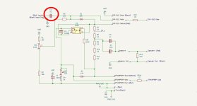
I am looking at the schematics of the 2022 Front-End and your amp. My assumption is that the C3 cap on the 2022 FE and the C1 cap on your amp are coupling caps and the main function is to block DC. If this is the case, we have 2 caps in series (3.3uF and 4uF). Would it benefit the sound (lower frequencies) to remove one of these caps and replace it with a wire?
If yes, which one?
Attachments
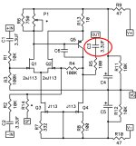
Yes they are for blocking DC, so you can remove one if you wish. Since they are similar in value, you can remove the one that you think is "inferior".
Keeping them both in place affects the low frequency response only a small amount, approximately 0.1 to 0.2dB at 10Hz.
Or you can compare them by listening. The choices are keep both, remove the 3.3uF, or remove the 4uF.
You may or may not hear any difference. 🤓
Keeping them both in place affects the low frequency response only a small amount, approximately 0.1 to 0.2dB at 10Hz.
Or you can compare them by listening. The choices are keep both, remove the 3.3uF, or remove the 4uF.
You may or may not hear any difference. 🤓
Hi Ben,
I have been playing in stereo for the last 3 hours through my test playlist 🙂.
This amp is crazy good. I compare it to Aleph J (without coupling cap) which sounds very good and all my friends love it.
SIT is definitely in a different league. Dead quiet - not even a little hiss or noise from very sensitive horns.
Scale and soundstage isvery big - a wall of sound with great depth 🙂. I was expecting that to be honest.
The bass is very detailed and precise. I can hear parallel low frequency sounds that the Aleph J presents as one note.
Midrange is very nice with volcals sounding very real and reach.
I think the biggest surprise for me is the background detail. It is not easy to describe, but to me this amp is able to emphasize and present background layers in a way that your ears are very attracted to it.
Very dynamic and smooth sound overall.
Thanks once again Ben.
Hi Decek,
I am glad that you are enjoying your new amps, that you are enjoying their sound and also their lack of noise. I too have highly sensitive speakers so noise abatement was one of my goals. Design, layout, and construction detailing all play a part in a quiet amp. You did a great job with the construction.
It has been nearly four years since I first built this amp with strip board and I am still enjoying the amps immensely, although I am so used to their sound that they now seem ordinary. 🙂
Ben, I haven’t forgotten those measurements, super busy. Can I get the Gerbers for Mofo Fokin Mu follower?
- Home
- Amplifiers
- Pass Labs
- Single Ended Tokin SIT THF-51S Common Drain Mu Follower Amplifier, 45W?