The metalwork is quite simple, especially if you can purchase aluminum pieces precut to size.
Then all you need to do is drill holes in the plate, and drill and tap holes in the heatsinks. To make tapping easier, locate the holes between the fins of the heatsinks. Also use 4mm screws as a 4mm tap is much less likely to break than a 3mm tap.
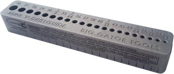
A drill press is handy but not necessary. I do all my drilling with a hand held drill. I do use a drill guide to help keep the holes perpendicular to the heatsink. I have the Big Gator drill guide, which is quite pricey, but there are others not as pricey. I only have experience with the Big Gator version and it works for me. I also use it to keep the tap vertical when starting the tap in the holes.
Then all you need to do is drill holes in the plate, and drill and tap holes in the heatsinks. To make tapping easier, locate the holes between the fins of the heatsinks. Also use 4mm screws as a 4mm tap is much less likely to break than a 3mm tap.
A drill press is handy but not necessary. I do all my drilling with a hand held drill. I do use a drill guide to help keep the holes perpendicular to the heatsink. I have the Big Gator drill guide, which is quite pricey, but there are others not as pricey. I only have experience with the Big Gator version and it works for me. I also use it to keep the tap vertical when starting the tap in the holes.
Attachments


Hi
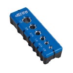
If I may add, I used to tap my hole with a manual hand tap…it would take forever and I would sometimes break the tap in the hole..I have now discovered this tap that I use with my hand drill, it’s amazing. 6-32 drill tap
I make sure to use some oil before taping.
One very important trick to never break your tap is to set your hand drill to about 1/2 its full torque. On mine I adjust the clutch to about 6 out of 14.
Thanks for the hints. I will order aluminum bars 300 x 50 x 10 mm (I hope this is big enough) and M4 drill tap 🙂
Yes, as wide as possible is best.
This amplifier will get hot! The 3U/400 chassis may be borderline for dissipation, especially if the ambient temperature is high.
Nelson did some chassis dissipation tests: https://www.diyaudio.com/community/threads/store-heat-sinks-thermal-numbers.392902/
The 3U/400 was not tested though. The 4U/300 was tested and it was good for 83W per side. The 4U/300 has approximately the same heatsink area as the 3U/400. So that is a good indication that the 3U/400 may work, but good coupling of the two 200mm wide heatsinks on each side of the chassis is essential.
There is progress!
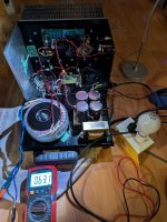
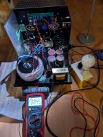
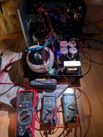
The Antek 30V+30V 500VA transformer is installed.
It was tested for proper AC connection, and then connected to the power supply CLC filter for DC, both unloaded.
No sparks, no drama, so all is good.
Unloaded the DC voltage was 84.5V. This exceeded the 80VDC rating of the power supply capacitors but I expect the voltage to drop below 80V once the power supply is loaded by the amplifier circuit. Temporary short term voltage overload is addressed by Chemi-Con, the manufacturer of the capacitors:
Rated Voltage
If the applied voltage exceeds the rated voltage of the capacitor, the capacitor may be damaged from an increase in leakage current. When using a capacitor with an AC voltage superimposed on a DC voltage, care must be exercised so that the peak value of the AC voltage plus the DC voltage does not exceed the rated voltage.
When capacitors are connected in series, the voltage distribution across the series may not be uniform. This is due to the normal DC leakage distribution and should be considered in the design process by using a higher rated voltage capacitor and/or using balancing resistors in parallel with each series capacitor.
Surge Voltage
The surge voltage rating is the maximum over-voltage including DC, peak AC and transients to which the capacitor may be subjected for short periods of time (not exceeding 30 seconds every 5 minutes). According to JIS C5141, the test shall be conducted for 1000 cycles at room temperature under test condition W of JIS C5141or at the maximum operating temperature under test condition B and C of JIS C5141. Under test, the capacitor shall have voltage applied through a current limiting resistor of 1000 ohms without discharge. After test, the electrical characteristics of the capacitor are specified in JIS C5141. Unless otherwise specified, the rated surge voltages are as follows:
Rated Voltage (V).............6.3 10 16 25 35 50 63 80 100 160
Rated Surge Voltage (V) 8 13 20 32 44 63 79 100 125 200
Rated Voltage (V)............. 200 250 315 350 400 450 500
Rated Surge Voltage (V) 250 300 365 400 450 500 550
From: Chemi-Con: Guidelines for Using Aluminum Electrolytic Capacitors
Before I connect the amplifier board to the power supply I need to insert a resistor (0.1R) into the string of 0.1R resistors between the Mosfet and SIT, in order to get the Iq into the proper range.
Attachments
Last edited:

Ben, I've said it before, and I'll say it again; the time you take to share your methodology / approach to builds and the details of your process are an incredible help to DIYers everywhere. 

The joy of DIY is a successful build, one that works properly on first power-up. That is what I strive for. 🤓
There is no joy when a project does not function properly when powered up. 💩
There is no joy when a project does not function properly when powered up. 💩
The DISPAIR of a failed attempt is a real thing.  But perseverance to success is why we keep coming back. It's all thrilling.
We succeed because we are willing to fail.
But perseverance to success is why we keep coming back. It's all thrilling. We succeed because we are willing to fail.
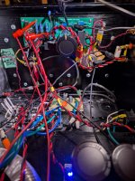
So I modified the amp board based on the LTSpice simulation. I added the 0.1R resistor between the Mosfet and SIT.
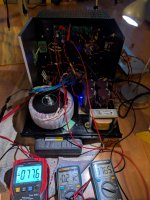
There were no problems with power up. I started with the Dim Bulb Tester just in case, but no issues, so next was full power.
However when adjusting Iq, the maximum I could get was 2.12A. This showed that although simulations are very useful to get a circuit working, real life results may not mirror simulation results exactly. So I made a quick change, shorting R4 on the amplifier PCB and that did the trick. I was able to dial in 3A, and the power supply settled in at 76V.
Power and distortion testing next.
Attachments
-
 THF-51S MUFF 75VDC Measured Operating point.jpg565.6 KB · Views: 203
 -
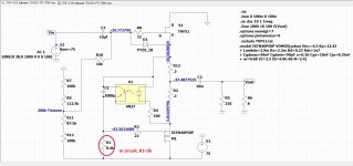 CCS mod for 75VDC, in circuit vs LTSpice.jpg382.2 KB · Views: 233
 -
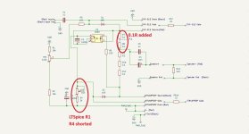 CCS mod for 75VDC Revise R4.jpg73.4 KB · Views: 224
 -
 THF-51S MUFF 75VDC Max Iq before shorting R4.jpg514.5 KB · Views: 201
 -
 THF-51S MUFF 75VDC PCB R4 shorted.jpg560.6 KB · Views: 150
I did some FFT measurements and there were no surprises.
The first set were done with the DIY FE2022 preamp providing voltage gain. This preamp has a 62V power supply and it was able to provide enough signal voltage output to get 35W @ 8R from the power amp.
I used my 2SK79 preamp to test the amplifier to maximum power output. This preamp has higher distortion than the DIY FE2022 so I repeated some of the lower power output FFT measurements for comparison.
Here are the FFTs with the DIY FE2022 providing voltage amplification:
Attachments
-
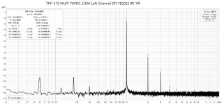 THF-51S MuFF 76VDC 2.93A Left Channel DIY FE2022 8R 1W.jpg195.6 KB · Views: 99
 -
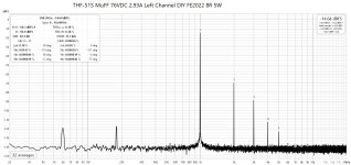 THF-51S MuFF 76VDC 2.93A Left Channel DIY FE2022 8R 5W.jpg195.5 KB · Views: 101
 -
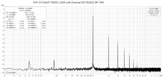 THF-51S MuFF 76VDC 2.93A Left Channel DIY FE2022 8R 15W.jpg195.8 KB · Views: 90
 -
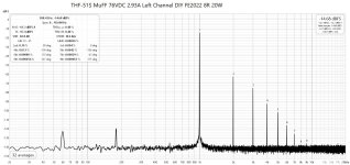 THF-51S MuFF 76VDC 2.93A Left Channel DIY FE2022 8R 20W.jpg196.4 KB · Views: 94
 -
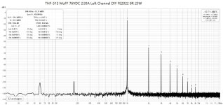 THF-51S MuFF 76VDC 2.93A Left Channel DIY FE2022 8R 25W.jpg196.3 KB · Views: 88
 -
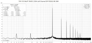 THF-51S MuFF 76VDC 2.93A Left Channel DIY FE2022 8R 30W.jpg196.7 KB · Views: 89
 -
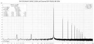 THF-51S MuFF 76VDC 2.93A Left Channel DIY FE2022 8R 35W.jpg196.2 KB · Views: 104
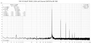
And here are the FFTs with the 2SK79 preamp providing the voltage amplification:
Attachments
-
 THF-51S MuFF 76VDC 2.93A Left Channel 2SK79 Pre 8R 1W.jpg196.5 KB · Views: 94
 -
 THF-51S MuFF 76VDC 2.93A Left Channel 2SK79 Pre 8R 10W.jpg196 KB · Views: 90
 -
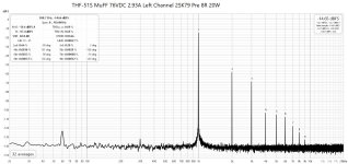 THF-51S MuFF 76VDC 2.93A Left Channel 2SK79 Pre 8R 20W.jpg195.8 KB · Views: 86
 -
 THF-51S MuFF 76VDC 2.93A Left Channel 2SK79 Pre 8R 30W.jpg195.9 KB · Views: 96
 -
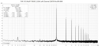 THF-51S MuFF 76VDC 2.93A Left Channel 2SK79 Pre 8R 40W.jpg196.7 KB · Views: 83
 -
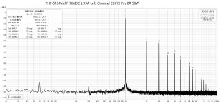 THF-51S MuFF 76VDC 2.93A Left Channel 2SK79 Pre 8R 50W.jpg197.1 KB · Views: 91
 -
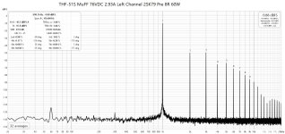 THF-51S MuFF 76VDC 2.93A Left Channel 2SK79 Pre 8R 60W.jpg198.1 KB · Views: 85
 -
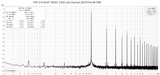 THF-51S MuFF 76VDC 2.93A Left Channel 2SK79 Pre 8R 70W.jpg199.5 KB · Views: 95
- Home
- Amplifiers
- Pass Labs
- Single Ended Tokin SIT THF-51S Common Drain Mu Follower Amplifier, 45W?