
Both channels up and running. Comfortably driving a pair of LRS+. The sound….is a thing of beauty. Lottery amp on steroids. Magnepan should demo with these amps.
Superb dynamics and low level detail. And best controlled bass I’ve heard on the Maggie’s so far - mainly Class D used previously.
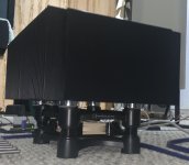
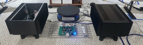
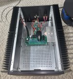
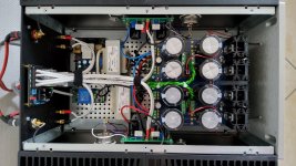
Cautiously biased at 2.3A. Sadly the chassis’ are not mine so this is only a temporary home - hence the power and input connectors out the IEC inlet hole.
Babysitters are running continuously in low-noise mode and heatsink temps outside/opposite SITs around 63 degrees C. Probably need 5U’s. Awhile ago, while looking at a pair of ISO Acoustics stands I had, it dawned on me that the Noctua fans I’d bought (to satisfy ZM 🙃) fit perfectly in the center of the stands. All I needed was a means of support. Four corner supports that slip over the stand’s uprights were 3D printed and it worked out well - stands get the amps up in the air sufficiently to allow good inflow under the fans and the chassis allowed almost exact location of the feet to fit the stands. Fans are completely inaudible a foot away - 8.6dBA with the reduced speed low-noise cable that came with them.
Now I have to decide which limb to part with to acquire two 5U chassis.
You were right, Ben - I love the sound. Thanks again for the boards and your efforts. And, to Papa, I hope I get to thank you lots more for all the fun and great designs - these SITs are…magic!
Superb dynamics and low level detail. And best controlled bass I’ve heard on the Maggie’s so far - mainly Class D used previously.
Cautiously biased at 2.3A. Sadly the chassis’ are not mine so this is only a temporary home - hence the power and input connectors out the IEC inlet hole.
Babysitters are running continuously in low-noise mode and heatsink temps outside/opposite SITs around 63 degrees C. Probably need 5U’s. Awhile ago, while looking at a pair of ISO Acoustics stands I had, it dawned on me that the Noctua fans I’d bought (to satisfy ZM 🙃) fit perfectly in the center of the stands. All I needed was a means of support. Four corner supports that slip over the stand’s uprights were 3D printed and it worked out well - stands get the amps up in the air sufficiently to allow good inflow under the fans and the chassis allowed almost exact location of the feet to fit the stands. Fans are completely inaudible a foot away - 8.6dBA with the reduced speed low-noise cable that came with them.
Now I have to decide which limb to part with to acquire two 5U chassis.
You were right, Ben - I love the sound. Thanks again for the boards and your efforts. And, to Papa, I hope I get to thank you lots more for all the fun and great designs - these SITs are…magic!
Attachments

Derek, I am glad you like the sound. If you need power this is a great way to get it. It does run hot because of that though. In a month or so, I will have them back in my system for great music and auxiliary room heating.
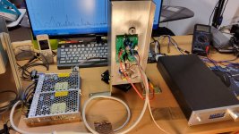
A month ago ZM asked me if it is da pudding in there and here is a proof with some sweet sugar.difference is THF51 (to said amp)...
So, let's talk about these fantastic factors: Iq, my trusty 1.45 A companion, and it's a real trooper,
staying steady after a whole 35 minutes - no wobbling, no shaky legs, 0 mV +/- 1 mV offset only.
And when it comes to powering up and down, it's a real drama queen. On the way up,
it lets out a tiny "excuse me" in the form of a very light fart (well, we all have our quirks).
But when it's time to power down, it's like a ninja in the night - absolutely no signs of its presence.
In the world of real hardware, Iq is my unsung hero, and those quirky power-on moments just
add a touch of charm to the whole shebang. And now some porn of the nacked queen on the test bed

Attachments


Yes, the aim of this exercise was to eliminate the huge capacitor at the output and reduce the dissipated power with the bias current to a reasonable level (Pq < 70W and Iq < 1.5A).
At the same time, the performance in the first watt range should be maintained compared to a single power supply with an output cap

At the same time, the performance in the first watt range should be maintained compared to a single power supply with an output cap
Hi,
Awesome amp Ben!
Would you recommend any changes to R2/R5/R13 to drive 18 Ohm horn speakers?
Thanks.
Awesome amp Ben!
Would you recommend any changes to R2/R5/R13 to drive 18 Ohm horn speakers?
Thanks.
You could leave it as is.
If you want to experiment, especially if you have a distortion analyzer (simple one using a USB sound card and software such as REW works great), you can try adjusting the SIT bias voltage to vary the SIT Vds. Another tweak would be to vary the R2/R13 combination, keeping R2+R13=0.5 Ohm. Try 0.3 Ohm next to the SIT and 0.2 Ohm next to the mosfet.
Another way to experiment is to simulate the circuit in LTSpice. The distortion values from the simulation may not be the same as those that you get from measuring the actual amplifier, but the simulation results will give you an idea of the effects of the changes.
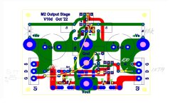
My exiting story with a SIT-muFF using a dual rail supply has finished in a monoblock chassis.
I was too lazy to design a new PCB and adopted one from the M2OPS project lying in my drawer (many thanks to EUVL for making Gerber available) because of the similar topology. Making two cuts and two additional wire connections it seems to be a simple modification. Some shorter ones and a few holes for the second trimmer were quickly added and drilled.
PSU is standard for FW amp projects with CLC configuration giving +/-23.5 V dual rail.
Bias current was easily set to Iq = 1.4 A and offset was stable remaining within a few millivolts. Max output at 4 and 8 Ohm is halved as expected comparing with +60 V single rail supply. THD spectra also look good.
It is interesting that there is no thump while switch on and a negligible fart when switching off. There was no wandering DC offset observed within 3 months of almost daily use.
How does it sound? Is it something like 300B?
For me it seems to be very clear and close to other single ended builds but the low end feels to be tight. Maybe I'm just imagining it but I am very happy to get rid of the huge capacitor at the output.
I would even put forward a thesis that the effect of a large output capacitor has a not insignificant sound effect that is usually perceived as more pleasant.
This is just how it sounds to me. Simply nicer. Why is then the ridding of all capacitors at output so important for me? Good questio😉
Attachments
-
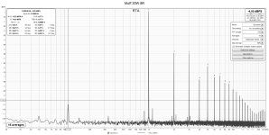
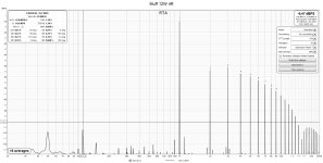 Muff_12W_4R.jpg352 KB · Views: 197
 -
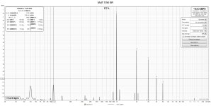
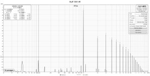 Muff_10W_4R.jpg347.8 KB · Views: 158
 -
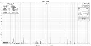
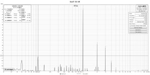 Muff_1W_4R.jpg345.5 KB · Views: 135
 -
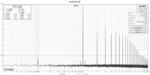 Muff_22W_8R.jpg362.6 KB · Views: 133
 -
 Muff_20W_8R.jpg363.7 KB · Views: 119
 -
 Muff_10W_8R.jpg343.4 KB · Views: 115
 -
 Muff_1W_8R.jpg343.1 KB · Views: 175
 -
 SIT-MUFF_PCB_back.jpg309.1 KB · Views: 197
 -
 SIT-MUFF_PCB.jpg397.2 KB · Views: 227
 -
 M2OPS_MuffTHF51S.jpg188.8 KB · Views: 230
 -
 20240416_171130.jpg372.1 KB · Views: 226
I have been following this thread quietly but with great interest for some time, especially ACnotDC's dual rail version without a large output capacitor, which would also be more in line with my personal preferences (perhaps based on prejudices).
I have a couple of THF51-S left and two huge aluminium (7kgs/unit) heat sinks from defective solar inverters that should easily suffice 3A of quiescent current, maybe even more.
Now the question arises as to whether I should build Ben's version or a dual-rail version with approx. +/-30V based on ACnotDC's work.
@ACnotDC: Would you yourself build the dual-rail version again or recommend it to me? Could it be that the tighter low end you mentioned is due to the different operating points / lower bias current?
alexbo, if I have a choice to build an amp w/ or /wo a capacitor at the output, I would always go for a direct coupled one.
One could say I am biased and believe in myths. May be it is so or not, but I did it my way. Everyone of us has a personal preference and nobody is perfect.
There are some technical and practical aspects you should take in account before you make your mind up:
1. the output power of 45 W will be halved
2. if you want more Class A with a high bias current of 3 A or even more at single +60 V, then it is an easy decision
3. choosing a right operating point for a THF-51S is a great question regarding its Ptot = 400 W at max 600 V and 30 A but not impossible. The best example is the newest SIT-4 😎
3. there are no Gerber files for my version, I have adopted a PCB of EUVL's M2OPS
4. SQ: a tighter low end, I have mentioned, might come from the different operating point, but I was thinking mainly about the lack of the output capacitor here
5. my version doesn't use a big hockey puck, a smaller IXTH90P10P in TO-247 is enough
Maybe the other builders can also give you some tips to help you make your decision🙂
Last edited:
It's a personal preference from my point of view. Some do not like capacitors and some do not dislike them. I am in the latter group.
I also like the security of the capacitor protecting my speakers in the event of an amplifier malfunction.
Re: tighter low end: ACnotDC - Was your comparison with single ended tube amplifiers only? Or with a similar THF-51S amplifier with output capacitor? I have had single ended tube amplifiers in the past and they did not have tight bass, but they also had much lower power output. I have no issues with the low end performance of this THF-51S amplifier with output capacitor.
Last edited:
Thanks for the quick reply. @Ben Mah: I am one of the former group 😉.
So I think I will work towards a dual rail circuit keeping the operating point of the single rail version.
I will take the fact that there are no Gerber files as an opportunity to dig deeper into KiCAD in the upcoming months.
Maybe I can integrate a frontend like FE2022 as well ...
But first I want to run simulations. I found a Spice model for the THF51-s in an earlier post. I hope it is the one you were all using. An IXTN40P50P model does not seem to be available, but I found one for the IXTK40P50P on the vendor's web page. IXTN40P50P and IXTK40P50P seem to be identical (including RthJC). I hope, this model works and is sufficiently accurate.
btw: Are there good reasons for not using the much cheaper TO-264 version? If not, I will give it a try, since I have plenty of TO-264 insulators left and would like to keep the connections short.
Tighter low end: Has anybody investigated damping factor (vs. frequency)?
@Ben Mah:
Yes, the only benefit of an output capacitor is that it protects your woofers from DC current appearance at the binding posts.
I have not claimed that this amp has low end performance issues, nor have I compared it with and without an output capacitor.
But I do feel that any capacitor in the signal path is one too many and creates its own sonic signature.
It is enough to look at what a 40 Hz square wave looks like when it passes through a 10mF capacitor and compare that to a 10mm copper wire.
@alexbo:
The measured DF at 1 kHz is 12 only.
LTSpice models that I used in my simulations:
.model IXTN40P50P VDMOS(pchan Vto=-4.5 Kp=12.43
.SUBCKT thf51 D G S ; Drain Gate Source
+ PARAMS: MU=43.571 X=1.494 K=1.339 N=0.902 VCT=0.831 RG=5MEG
*--------------------------------------------------
B1 D S I=K*PWR(URAMP((V(G,S)+VCT)+(N*LN(V(D,S))+(V(D,S)/MU))),X)
FOR MULTISIM COMMENT OUT ABOVE LINE () AND UNCOMMENT NEXT LINE
*B1 D S I=K*PWR(MAX((V(G,S)+VCT)+(N*LN(V(D,S))+(V(D,S)/MU)),0),X)
R1 G S {RG}
CGS G S 5000P
CGD G D 5000P
CDS G S 0P
.ENDS thf51-1x0063
I used the hockey puck version of the mosfet for its power handling capability. I also chose the hockey puck version because others have used that size for similar amplifiers. I run it at 3A now and about 30V, so approximately 90W. The SOA of the device needs to be examined and the ability of the device to operate safely at DC and actual operating temperature needs to be reviewed. The TO-264 version may work as long as it has adequate heat management and is operated within its SOA.
.model IXTN40P50P VDMOS(pchan Vto=-4.5 Kp=12.43
- Lambda=2.9m Rs=2.2m Rd=0.23 Rds=1e7
- Cgdmax=96nF Cgdmin=90pF a=0.26 Cgs=10nF Cjo=8.35nF
- m=0.68 VJ=2.5 IS=4.0E-06 N=2.4)
.SUBCKT thf51 D G S ; Drain Gate Source
+ PARAMS: MU=43.571 X=1.494 K=1.339 N=0.902 VCT=0.831 RG=5MEG
*--------------------------------------------------
B1 D S I=K*PWR(URAMP((V(G,S)+VCT)+(N*LN(V(D,S))+(V(D,S)/MU))),X)
FOR MULTISIM COMMENT OUT ABOVE LINE () AND UNCOMMENT NEXT LINE
*B1 D S I=K*PWR(MAX((V(G,S)+VCT)+(N*LN(V(D,S))+(V(D,S)/MU)),0),X)
R1 G S {RG}
CGS G S 5000P
CGD G D 5000P
CDS G S 0P
.ENDS thf51-1x0063
I used the hockey puck version of the mosfet for its power handling capability. I also chose the hockey puck version because others have used that size for similar amplifiers. I run it at 3A now and about 30V, so approximately 90W. The SOA of the device needs to be examined and the ability of the device to operate safely at DC and actual operating temperature needs to be reviewed. The TO-264 version may work as long as it has adequate heat management and is operated within its SOA.
Attachments
Last edited:
That will depend entirely on the load resistance of the circuit.It is enough to look at what a 40 Hz square wave looks like when it passes through a 10mF capacitor
Thanks for the model an the comments. The IXTN40P50P model provicdd by IXYS seem to be broken or at least not compatible with LTSpice.
I managed to modify the schematic for +/- 33V rails and about 3A of quiescent current.
Simulation results look promising so far. Dissipation of is approx. 100W per device, as expected. Still need to check SOAs.
IXTN40P50P vs. IXTK40P50P: RthCS of the latter three times as high. Nevertheless, 0.5K/W heatsink should be sufficient.
Greetings folks!
I was curious if I might be able to snag those Gerber files for the amp and power supply?
I'm a bit late to the party, but, I would absolutely love to build this great little amp!
I was curious if I might be able to snag those Gerber files for the amp and power supply?
I'm a bit late to the party, but, I would absolutely love to build this great little amp!
- Home
- Amplifiers
- Pass Labs
- Single Ended Tokin SIT THF-51S Common Drain Mu Follower Amplifier, 45W?