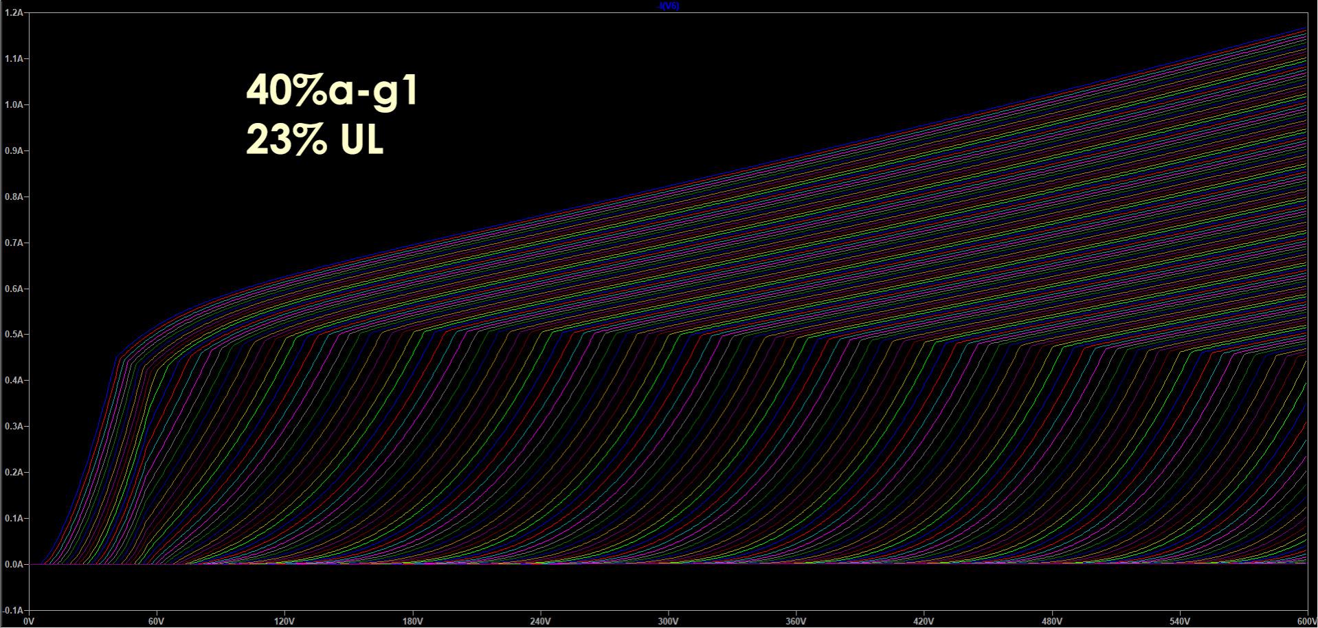
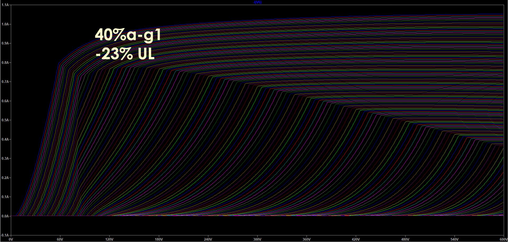
Some comparative curves for a-g1 plus UL and the related LTSpice file.
Attachments

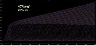

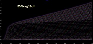
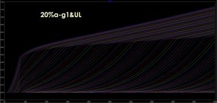
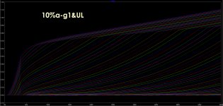
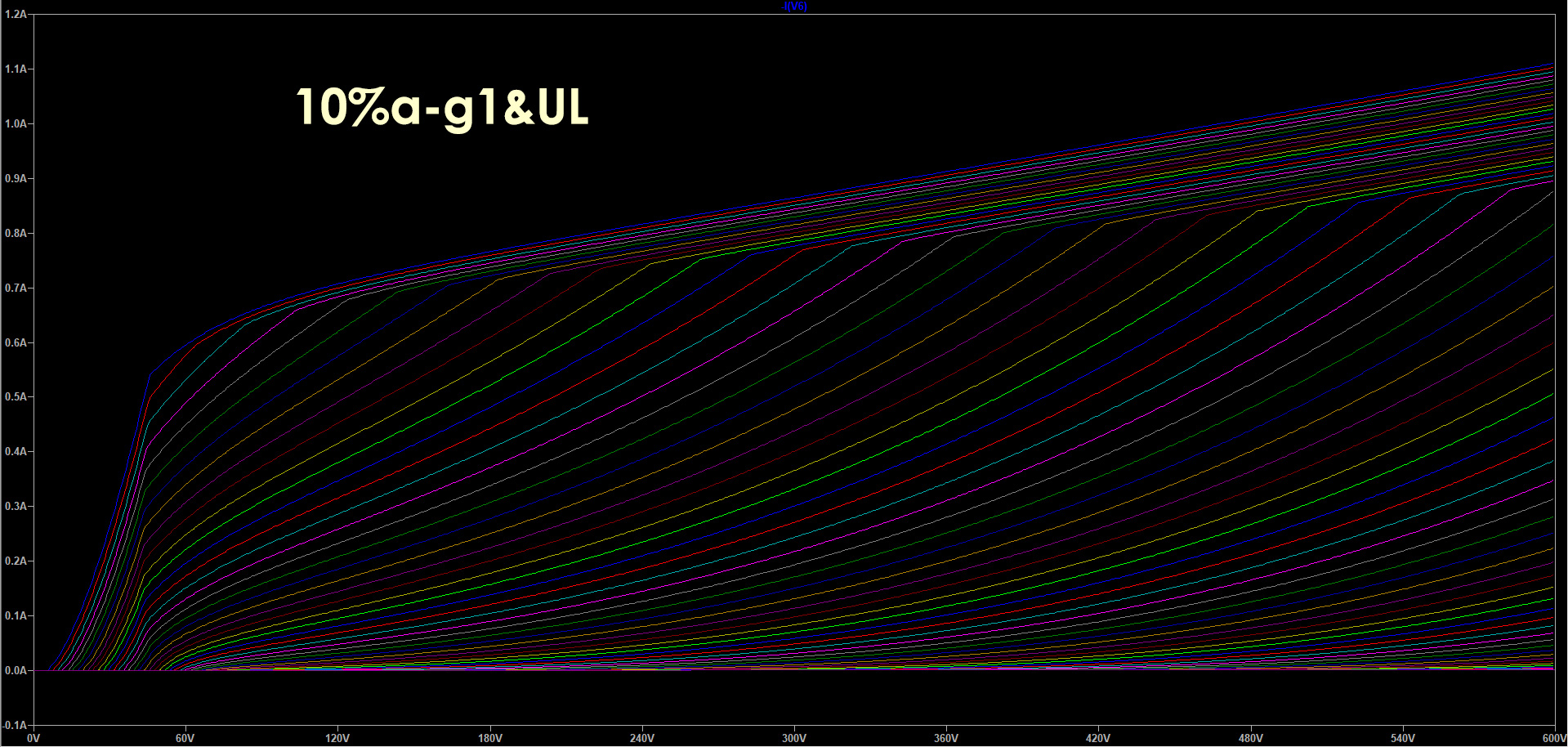
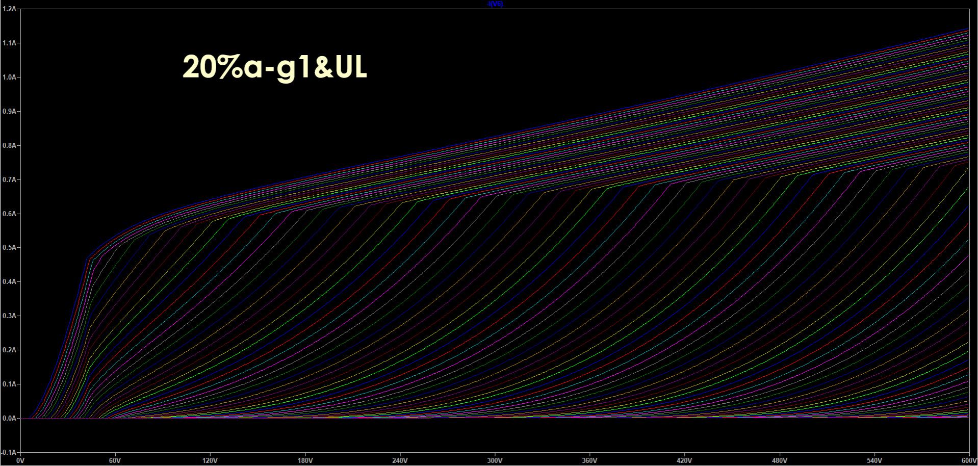
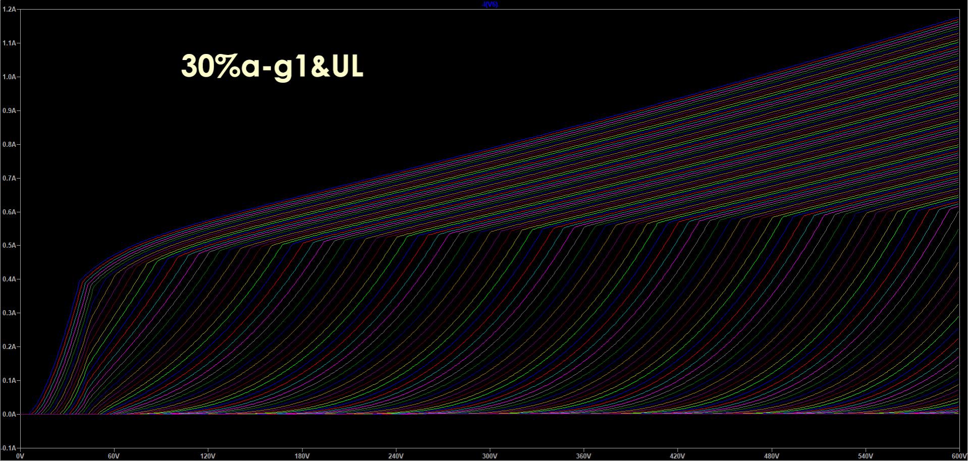
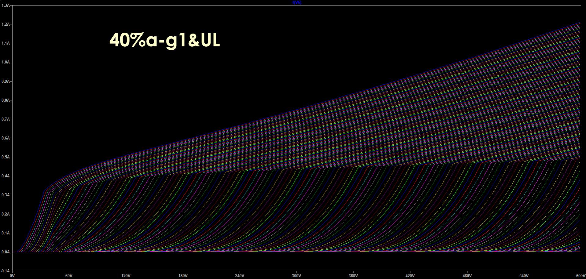
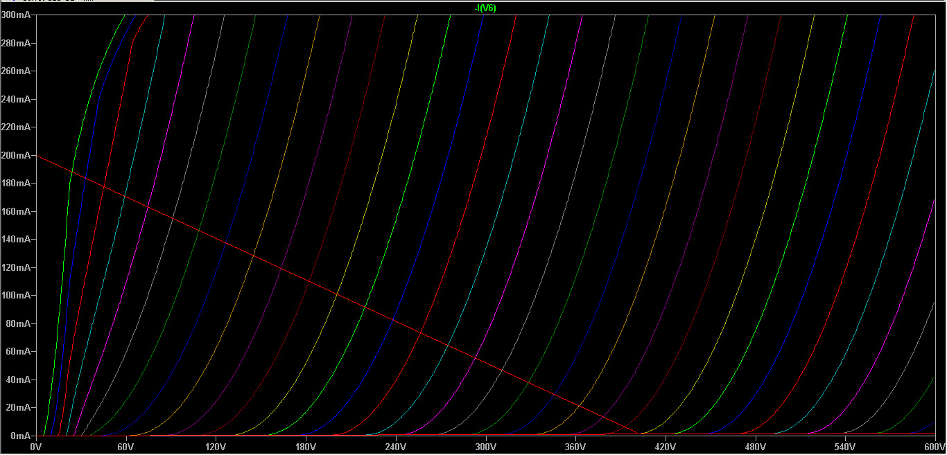
What I notice is that with 10% a-g1 feedback, curves seem more linear, whilst with higher percentages there's an area with lower gain around the knee.
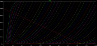
Last test is just to show the prevalence of the a-g1 compared to a-g2 (UL) feedback.
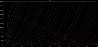
Last plot is a "super-pentode" like configuration, with a-g1 feedback.
Last test is just to show the prevalence of the a-g1 compared to a-g2 (UL) feedback.
Last plot is a "super-pentode" like configuration, with a-g1 feedback.
What I notice is that with 10% a-g1 feedback, curves seem more linear, whilst with higher percentages there's an area with lower gain around the knee.
Last test is just to show the prevalence of the a-g1 compared to a-g2 (UL) feedback.
Last plot is a "super-pentode" like configuration, with a-g1 feedback.
The last one being like the Mac U-C design, yes? Works towards keeping g2-k voltage constant, or at least less variable.( not sure of the magnitude of cathode voltage swing ).
cheers,
Douglas
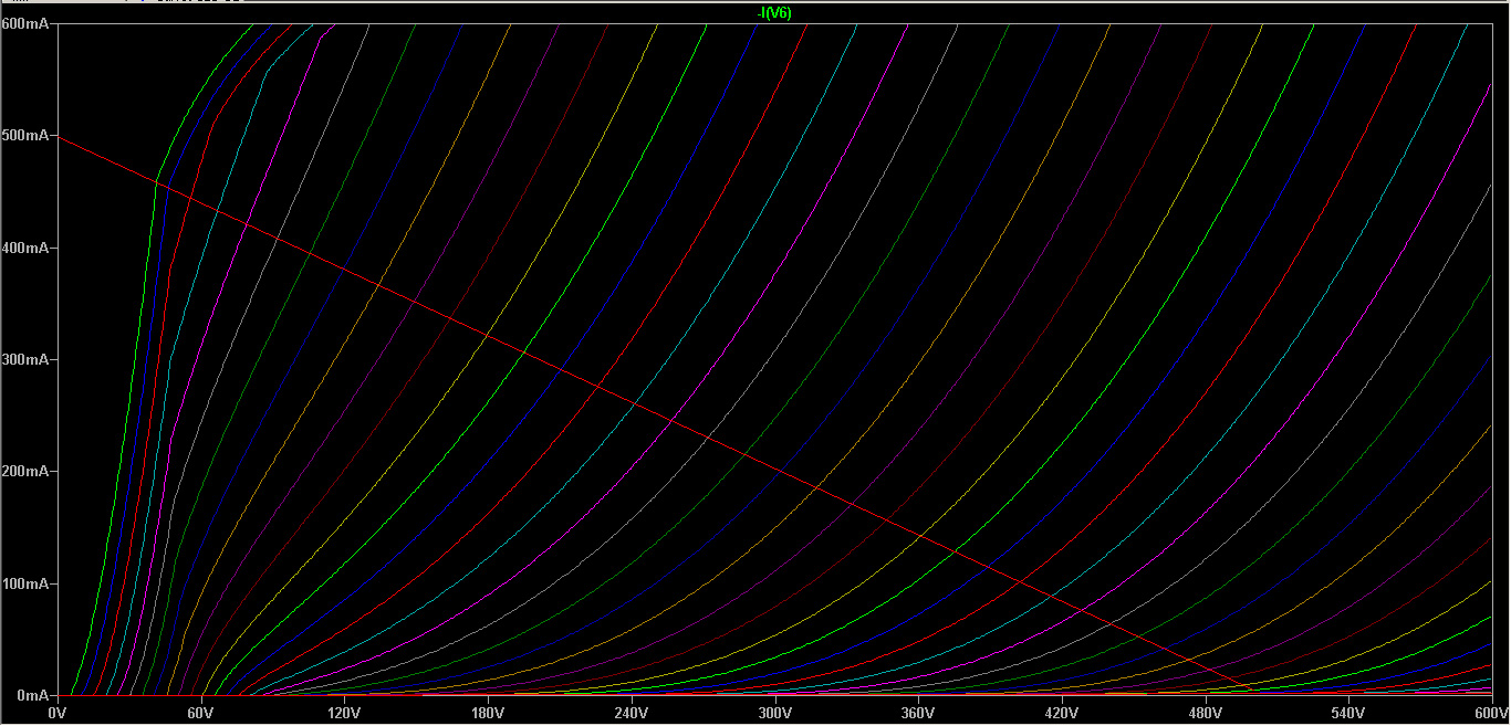
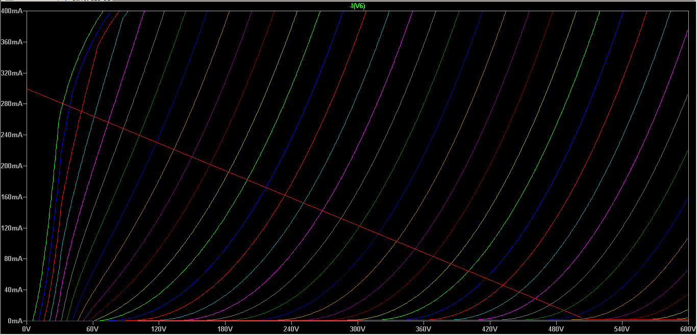
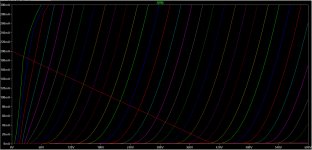
I update this thread with some curves of this combined CED&UL.
All curves are with 22% a-g1 and 23% UL:
KT88 with 4k Raa loadline and 500V (more than 80Wrms)
EL34 with 6.6k Raa loadline and 500V (more than 60Wrms)
EL84 with 8k Raa loadline and 400V (more than 30Wrms)
I've not yet built it because I'm moving to a new house where I'll have more space to experiment. I confirm that a-g1 feedback is way more effective than a-g2/UL, but this was clear to anyone.
The synergic effect of UL is that we can "focus" the curves around the loadline (together with the screen resistor) by chosing the right amount of it and gain some more linearity and DF, plus (last but not least) simplifying the power supply so reducing costs and complexity.
See it on the opposite side: If you have an output transformer already on hand or you can find a cheap one, you can play with B+ voltage and a-g1 feedback to find the sweet spot for that specific tube.
The very low internal resistance of the tube in this scenario will allow a weak output transformer to increase its bandwidth and perform better. Again giving better results with lower costs.
I've ordered a bunch of FQP3P50 to perform some tests.
In attachment you can find the guidelines to use those pmosfets in linear mode.
Attachments
Tikiroo you are totally right!
I've used class B part of PP files for the loadlines and now I can no more modify the previous post.
I will ask moderators to do please modify/delete my previous post.
I've used class B part of PP files for the loadlines and now I can no more modify the previous post.
I will ask moderators to do please modify/delete my previous post.
If we stick to SE, the transformation to PP consideration is easy. Just apply an OPT with double the SE plate load. That is about all I'd consider building anyway. Two SE amps, bridged( with balanced input ), and sharing an OPT.
cheers,
Douglas
cheers,
Douglas
Hi Douglas,
if you read the incipit of this thread, I did the opposite: started with the PP and then open this SE thread.
if you read the incipit of this thread, I did the opposite: started with the PP and then open this SE thread.
Simulation is all fine, unfortunately LtSpice does not model transformers too well. And the modelling is done with a pure resistance load which speakers are not.
This has all the potential of instability like the Williamson amplifier that was only marginally stable and needed a specific wound OPT.
I do wonder why the hybrid approach, the logic of the approach eludes me.
This has all the potential of instability like the Williamson amplifier that was only marginally stable and needed a specific wound OPT.
I do wonder why the hybrid approach, the logic of the approach eludes me.
Thanks Amadeus,
may I ask you what similarities do you see with the Williamson, that lead you to claim this will be an unstable circuit and will need special OPTs?
may I ask you what similarities do you see with the Williamson, that lead you to claim this will be an unstable circuit and will need special OPTs?
Simulation is all fine, unfortunately LtSpice does not model transformers too well. And the modelling is done with a pure resistance load which speakers are not.
This has all the potential of instability like the Williamson amplifier that was only marginally stable and needed a specific wound OPT.
I do wonder why the hybrid approach, the logic of the approach eludes me.
There were many Williamson amps done commercially with a not small group of OPT's. Some were better than required, some resulted in nearly unstable amps. That instability has quite well-analyzed roots.
Not seeing how this source follower drive to the cathode is going to result in instability. The FB path is quite short, and missing most of the reactive elements found in a Williamson.
cheers,
Douglas
The instability that I see is not linked to the OPT, but to the fact that both tubes will have positive gain (output in phase with the input), and globally a very high gain, so unwanted positive feedback may happen and lead to oscillations.
But this is something that can be solved with a good layout.
But this is something that can be solved with a good layout.
Last edited:
Probably EL84 won't survive UL north of 350V.... EL84 with 8k Raa loadline and 400V (more than 30Wrms)...
Hi indra1,
with this configuration of almost equal a-g1 and a-g2 feedbacks, Vg2-k will be almost constant and around 320V (considering 22%).
This is because driving the cathode, when its voltage goes down, plate goes down as well, so does g2. They are following each other.
EDIT: added percentages and better explanation of the reasons.
Last edited:
Sorry, I need to reply on evenings when I have time and data with me, not during coffee breaks.
What I wrote here above is not correct, I will integrate and correct during the weekend.
In any case, with this configuration Vg2-k is quite constant and well below limits.
What I wrote here above is not correct, I will integrate and correct during the weekend.
In any case, with this configuration Vg2-k is quite constant and well below limits.
Last edited:
Thanks, I've read about that, but never heard live.
It can be done something similar, but then limits will become the heat dissipated by the pMosfet and the ability to have clean huge swings from the driver.
It can be done something similar, but then limits will become the heat dissipated by the pMosfet and the ability to have clean huge swings from the driver.
Thanks Amadeus,
may I ask you what similarities do you see with the Williamson, that lead you to claim this will be an unstable circuit and will need special OPTs?
1) You have not answered the question of the rationale behind using a hybrid approach.
2) I see motorboating coming up, potentially even oscillation.
3) You have not addressed the wildly fluctuation heater-cathode voltage.
4) Unnecessary complex, in 10 years time you may not be able to get a part and have to "improvise". The strength of a tube amplifier (if build properly) is that tube amplifiers (like a McIntosh, like a Quad II) can still work in 50 years time. What about your solid state parts, do you know if your parts are available in 50 years time?
IMHO you are ending up with the worst of either solid state or of tube technology.
I feel you quite upset, as we were saying at the beginning of the thread, please refer to this thread for the basics of cathode driving (but fixed g2 instead of UL): UNSET is coming?
1) You have not answered the question of the rationale behind using a hybrid approach.
2) I see motorboating coming up, potentially even oscillation.
3) You have not addressed the wildly fluctuation heater-cathode voltage.
4) Unnecessary complex, in 10 years time you may not be able to get a part and have to "improvise". The strength of a tube amplifier (if build properly) is that tube amplifiers (like a McIntosh, like a Quad II) can still work in 50 years time. What about your solid state parts, do you know if your parts are available in 50 years time?
IMHO you are ending up with the worst of either solid state or of tube technology.
I have not kept up with the latest twists in Zintolo's schematic, but the basic concept comes from work I have done. The schematic in the first post of this thread is similar to my UNSET design. Links to the design and several versions are in post #15 of this thread.
1) The rationale that I used for coming up with this concept was me looking for a way to get triode like performance from TV sweep (line output) tubes that have a restrictive screen grid voltage rating, and to do so with a minimalist power supply. The cathode driven stage works well with a sweep tube and about a 10% voltage feedback ratio.
2) Since all stages in a given SE amp are in phase with this approach, instability is a valid concern. Extensive testing with several two stage SE amps from 4 WPC to 40 WPC have not revealed any instability. I have been listening to a 20 WPC version for over a year now, even played my guitar through it without issue. I also have a 20 watt single channel P-P using a pair of 50C5's, a 80 WPC P-P version using 6GF5's (same guts as a 6DQ6), and am testing an UNSET board with each channer driven out of phase into a P-P OPT at the 250 watt level. None have blown up or shown instability. all are real live working amps (not sims) that play into real speakers.
3) Since I am working with TV sweep tubes, I often use odd voltage tubes. The output stage heaters are running on a separate supply, usually an SMPS. That supply floats to the average of the cathode voltages on the two channels. With my low feedback ratios the H-K voltage is well below max spec.
4) Some SS parts will be gone in 50 years, but so will I. That's not stopping me from building some amps with parts that I have now, and keeping enough spares to last my lifetime.
I have not done much testing with conventional audio tubes like the 6550 or KT88 since they can be easily triode strapped.
- Home
- Amplifiers
- Tubes / Valves
- Single Ended: the pentode retaliation