The usual "shunt Schade" N Fdbk, with resistor from plate to grid 1 has a flaw in it. The grid 1 voltage swing corrupts the current Fdbk thru the Fdbk resistor. (power tubes are generally close to square law Vg1 to Ip, so Vg1 is not linear with output V, so not just a re-scaling)
The new cathode drive removes the interference to the N Fdbk. It also increases the power output possible with the tube, since plate V (and usually screen V) increases with drive V. (the Mosfet driver power input adds to the tube power output, but the overall gm characteristics remain very close to the original tube's gm character)
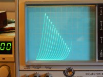
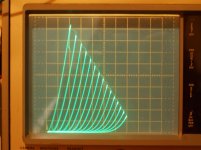
Using the "new series Schade" or "UnSET/CED" scheme allows TV Sweep tubes to be used in a triode like fashion without exceeding the grid 2 voltage specs. One can also select the Mu factor by the R ratio. This mode also provides better triode curves than are possible using the usual internal triode configuration, often challenging DHT triodes. A 6HJ5 Unset curve set below, left, followed by the usual 6HJ5 internal triode curves.
The new cathode drive removes the interference to the N Fdbk. It also increases the power output possible with the tube, since plate V (and usually screen V) increases with drive V. (the Mosfet driver power input adds to the tube power output, but the overall gm characteristics remain very close to the original tube's gm character)
Using the "new series Schade" or "UnSET/CED" scheme allows TV Sweep tubes to be used in a triode like fashion without exceeding the grid 2 voltage specs. One can also select the Mu factor by the R ratio. This mode also provides better triode curves than are possible using the usual internal triode configuration, often challenging DHT triodes. A 6HJ5 Unset curve set below, left, followed by the usual 6HJ5 internal triode curves.
Attachments
Last edited:
I'm sorry, I'm a newbie and I don't know the debate about UL do/don't. Can I ask you to point me to some readings? I can imagine is a matter of "the worst the output transformer is, the worst the UL feedback will be", so phase issues, transformer distortions reinjected into the output tube, etc...
Not a debate, just basic electronic principles. In a power tube, the input is normally introduced at g1 and the output extracted at the anode. The output suffers distortion due to nonlinear G1 to A transfer function. This distortion can be reduced with A to G1 feedback. By applying the feedback to G2 (UL), you are not compensating for G1-A distortion.
Empirically you will find that UL does reduce distortion in many cases, if not most. Your proposed experiment with variable ratios of A-G1 and A-G2 feedback should reveal the relative effectiveness of each. But I would not necessarily generalize the results. i.e. the results may be different for different tubes and operating conditions.
Last edited:
The usual "shunt Schade" N Fdbk, with resistor from plate to grid 1 has a flaw in it. The grid 1 voltage swing corrupts the current Fdbk thru the Fdbk resistor. (power tubes are generally close to square law Vg1 to Ip, so Vg1 is not linear with output V, so not just a re-scaling).
I'm sorry for being dim, but I don't follow this at all. Are you talking about the case when G1 current flows over part of the cycle? If not, then the feedback is doing exactly what it's supposed to do, correcting curves in the scaling factor of anode signal voltage to G1 signal voltage. Or, some combination of G1 and G2 in crazy modern designs.
Much thanks for any corrections,
Chris
No, nothing to do with grid 1 current, although that would produce distortion for sure with a current drive.
The usual "shunt Schade" scheme uses a current drive input with a current N Fdbk thru the Fdbk resistor into a grid 1 to ground resistor to set grid 1 V. It's just like the Fdbk resistor for an Op Amp. In the Op Amp case, there is enough loop gain to keep the input V variation almost to zero. But for a finite gain tube there is insufficient gain to hold the grid V steady. This variation of grid 1 V causes an error in the Fdbk current thru the resistor, since the grid end is not held at a constant V. (so only plate V would determine the current) If grid 1 V where accurately related to output plate V there would also not be a problem, that would just re-scale the Fdbk current.
But real power tubes are more like square law Vg1 to Ip, so a linear plate output V requires a non-linear input grid 1 V. This messes up the
Fdbk current in the Fdbk resistor. Distortion in the Fdbk signal is not good. UnSET fixes the problem by isolating the input signal V from the Fdbk current resistor.
Last edited:
But, if G1 voltage were accurately related to output plate voltage, there would be no distortion, by definition. Feedback *must* contain real-world distortion, properly phased, to work. Distortion in the feedback signal is essential.
As a means of keeping sweep valves' G2 voltages lower than plate voltages, the whole scheme seems very clever and successful, but I can't accept all of the explanations swirling around it.
Much thanks as always,
Mr. Whiney Poopy Pants
As a means of keeping sweep valves' G2 voltages lower than plate voltages, the whole scheme seems very clever and successful, but I can't accept all of the explanations swirling around it.
Much thanks as always,
Mr. Whiney Poopy Pants
The plate V distortion IS reflected back as expected. The problem is that the Fdbk current is proportional to the voltage difference across the Fdbk resistor, with plate V at one end and an assumed constant V at the other end. But the shunt scheme does not have constant V at the grid end like an Op Amp would, due to the low loop gain for a single loaded tube.
When I speak of distortion at the grid input, that is referring to the pre-anti-distortion needed to get the output undistorted.
In any case, curve tracing has shown that the UnSET scheme has better triode curves resulting than the older shunt Fdbk scheme did.
When I speak of distortion at the grid input, that is referring to the pre-anti-distortion needed to get the output undistorted.
In any case, curve tracing has shown that the UnSET scheme has better triode curves resulting than the older shunt Fdbk scheme did.
Last edited:
UnSET fixes the problem by isolating the input signal V from the Fdbk current resistor.
This is the part where I get lost. It seems like in both the series feedback arrangement and the parallel feedback arrangement, the Vg1-k gets added to a fraction of the plate swing to form the total drive voltage, which results in the same grid signal being applied to the tube. For a given feedback fraction, everything seems the same. I'd really like to understand what you are seeing but I'm having trouble. Unless you are talking about the current that leaks into the bias resistor in the parallel feedback case?
I have noticed that op amp manufacturers nearly always quote distortion numbers obtained with parallel feedback, because the results are typically much better. This doesn't seem to hold true in op amps. Op amps may have very high gain, but there is still a drive voltage that must be applied that causes errors. The errors are just smaller.
In Op Amps there is distortion from the common mode voltage variation of both + and - inputs swinging around. Using the inverting input avoids that.
The Op Amp specs don't deal with corruption of the current Fdbk resistor current itself when gain is low, because the Op Amps always have very high gain, which holds the inputs (difference) at virtual gnd.
Unset provides a clean copy of the plate V (attenuated) at grid 1 since the R divider goes to gnd. Then grid 1 to k takes the difference. All is well.
But for the shunt case you get a current Fdbk that is plate V - grid V across the Fdbk resistor. This is not the same as attenuated plate V alone. This then combines with an input drive current as the difference.
In any case, the triode curves come out better on the curve tracer for the UnSET case, that's all I care about.
The plate V distortion IS reflected back as expected. The problem is that the Fdbk current is proportional to the voltage difference across the Fdbk resistor, with plate V at one end and an assumed constant V at the other end. But the shunt scheme does not have constant V at the grid end like an Op Amp would, due to the low loop gain for a single loaded tube.
When I speak of distortion at the grid input, that is referring to the pre-anti-distortion needed to get the output undistorted.
This is the "argument of the excluded middle" about feedback, but it's not automatically, or even usually, true. If we've agreed that the disagreement is about an amplifier stage whose grid consumes no current, then we're discussing a current summing inverting stage, a classic anode follower.
An anode follower's grid is a node with equal and opposite signal (and other) currents from the source and from the feedback. No current flows into the grid, both sum to zero. I'm sure we can agree so far.
Where we seem to differ is whether or not any random amount of negative feedback reduces distortion. There are examples of pathological cases (Baxandall, Putzeys) of this not being monotonic, but should these cases be our model?
All good fortune,
Chris
Last edited:
Don, I think I finally understand what it is you are saying. It is going to take me some doodling when I have some time to sort my mind out on this.
The other thing I'm struggling with is that what you are saying seems to have very broad implications for the inherent superiority of one type of feedback over another. I just don't recall ever coming across such an assertion in any text I have read. My understanding was always that it didn't make a difference how voltage feedback was applied, except for the Zin implications.
I think I recall Douglas Self bringing up the CM input distortion in op amps and he noted that the LM4562 had markedly better performance than other op amps (must have some secret sauce in the input stage) but I think it still did better with parallel feedback. Maybe better but not perfect...
Hopefully you have some curves you can show that are a 1:1.
But for the shunt case you get a current Fdbk that is plate V - grid V across the Fdbk resistor. This is not the same as attenuated plate V alone. This then combines with an input drive current as the difference.
Right. To make it more accurate you would need an additional device to sum the two voltages before they are applied to the grid. Cathode drive makes for a clean sum without additional devices.
But: You need an active device at the cathode. For a grounded cathode, grid-driven tube you could use that same active device (mosfet in this case) to provide a clean summation at the grid.
Last edited:
The other thing I'm struggling with is that what you are saying seems to have very broad implications for the inherent superiority of one type of feedback over another. I just don't recall ever coming across such an assertion in any text I have read. My understanding was always that it didn't make a difference how voltage feedback was applied, except for the Zin implications.
I would guess that there is some similar gunk in the series model too for low loop gains, impedances likely. I just can't think of it at this late hour though.
I did have some tracings I posted a while back to compare the two versions, have to find them.
----------------------------------------------------------------
Right. To make it more accurate you would need an additional device to sum the two voltages before they are applied to the grid. Cathode drive makes for a clean sum without additional devices.
But: You need an active device at the cathode. For a grounded cathode, grid-driven tube you could use that same active device (mosfet in this case) to provide a clean summation at the grid.
Yes, agree. A grounded gate P Mosfet could isolate the feedback resistor when connected to the source. Drain then to the grid and current drive. That's what I was considering 1st, before jumping to the Mosfet in the cathode model. The cathode position does give the advantage of increased power output. George had the same idea and was working on it for years secretly. If he had a decent curve tracer he would have solved it 10 years ago. I checked it on the curve tracer and was immediately impressed that this could do DHT triode curves using cheap pentodes at high current.
Last edited:
I did have some tracings I posted a while back to compare the two versions, have to find them.
I've bookmarked this post of yours: Single Ended Output Tube for Lundahl LL9202 50mA
Comparing an older curve trace of "shunt Schade" with the "new" series Schade curves makes clear how much better the results are.
1) typical shunt Schade from Bartola's website (copyrighted): 307a with schade feedback (Part II) – Bartola(R) Valves
2) "new" series Schade
3) old style curves of 211 DHT tube
Right. To make it more accurate you would need an additional device to sum the two voltages before they are applied to the grid. Cathode drive makes for a clean sum without additional devices.
But: You need an active device at the cathode. For a grounded cathode, grid-driven tube you could use that same active device (mosfet in this case) to provide a clean summation at the grid.
No current flows into the grid. Source and feedback currents sum to zero at that node. Equal and opposite, and cannot be any other way. *Nothing else* is necessary. Stop worrying in voltage terms; it's only confusing things. Currents must sum to zero - end of story.
All good fortune,
Chris
Last edited:
May I ask you why you suggest 10% a-g1 feedback? More feedback will mean more power from the same output tube. Is it related to the reliability of the pmosfet, the sound (too much will de-tubify the sound), or the excessive swing needed to drive the finals to full power?Most of these simulations are variations of my UNSET, and CED push-pull amp designs.
Thanks
No current flows into the grid. Source and feedback currents sum to zero at that node. Equal and opposite, and cannot be any other way.
I believe there is a resistor from the grid to ground.
Looking at the shunt "Schade" curves from Bartola's site (Zintolo's post #34 above) (ignoring the topmost bend over variations due to saturation), the triode curves get slightly closer together going upwards. Opposite to normal triode curves which get further apart at higher current. Looking at the bottom ends, they appear to have reverse "roll-over" of normal triode curves too. (the bendy part at bottom has a sharper bend on the higher voltage curves, opposite to normal triodes, as shown by the yellow model simulated curves or the 211 curves at the bottom. )
While the UnSET curves have a near uniform spacing of constant Mu.
One can leave some natural "roll-over" effect in the curves by using a higher Mu factor in the UnSET R divider I believe.
So, basically, I see the Mu variation along a load line is opposite for "shunt" Schade versus normal triodes or UnSET. Although Unset can be adjusted for almost no Mu variation using a low Mu factor R divider.
Last edited:
Nomenclature is important,
A KT88 is a Beam Power tube; some call it a Beam Tetrode; some call it a Beam Pentode.
It has Beam Former Sheet Metal.
An EL34 is a Pentode.
Pentodes have a real suppressor grid.
Never the two shall meet.
The Key word is Beam, not pentode.
Just saying.
A KT88 is a Beam Power tube; some call it a Beam Tetrode; some call it a Beam Pentode.
It has Beam Former Sheet Metal.
An EL34 is a Pentode.
Pentodes have a real suppressor grid.
Never the two shall meet.
The Key word is Beam, not pentode.
Just saying.
I have a few issues with the curve comparison.
1. We're comparing a late production beam tube to a very old directly-heated pentode. The beam tube has 2.5x the transconductance.
2. Ale Moglia is running the pentode at a low screen voltage for the curves he is drawing so he is running over the Vg=0 line. We don't know where that line is, so we don't know where it is starting to affect things and steal current from the feedback network.
3. I don't think the feedback network impedances are comparable. The 6HJ5 curves appear to be getting right down to I=0 at even high voltages. I'm not sure how that is possible given that the feedback network is going to draw current there. Was it excluded somehow? The 307A curves show a clear lifting away from I=0 at higher voltages which will make it look like there is more curve laydown than there actually is.
4. The 307a has very soft knees which is going to cause a lot of compression in the curves as Ia rises and Va falls. Feedback will reduce this compression but as you can see it is still there. Series feedback would have the same issue, although the CED topology might gain some advantage because of the inherent screen drive, but that is another effect altogether and not due to the series feedback itself. 6HJ5 curves have some of the sharpest knees I have ever seen so won't suffer from any compression until right at saturation.
5. I'm not sure what the feedback fraction is on the 6HJ5 curves.
I don't think there is adequate control of variables to draw any general conclusions about curve shape differences in the two types of feedback from these two examples.
Do we have any examples of the same tube operating in both modes, with the same feedback fraction? It would also be nice to have series feedback curves with Vg2-k held constant so we can separate out the screen drive effects.
This would probably be a great job for a simulator. Maybe this will be what drives me to build some circuits in LTSpice. I have no idea how to get it to draw curves but I've seen it done so there must be a way.
- Home
- Amplifiers
- Tubes / Valves
- Single Ended: the pentode retaliation