Interesting stuff, well I will look forward to it, in the meantime I will do some reading on the technique itself. Very curious how the sound translates compared to a conventional power triode. The curves are very convincing, that's for sure.
Well I would say the PX25 is not practical due to price and rarity, but you have rekindled my interest in the type 50. The price for a NOS pair is not horrendous compared to high-end new production DHTs. Could build the amp with a TJ Fullmusic pair, then go NOS once finalized.
A 6.5K:8ohm 50mA 100H transformer really isn't a bad match for the 50 with its 1.8K Rp. Say a 450V 50mA bias point, LL9202 wired for 6.5K has 0.8dB in losses, would still give close to a 4W amplifier. Could also do 425V 50mA for tube longevity.
The driver would need to swing 170Vpk-pk. From my tubes on hand, trioded D3a seems a good choice. There is one other high gm pentode in my collection that would work well too, or other 300B driver types.
Filament for the 50 is 7.5V 1.25A, same as the 801A. If using Rod Coleman regulators, I have spare filament transformers on hand already. The big question would be 1:1 interstage vs. grid choke. It's an intriguing idea, extra since I have many of the parts. But let's be honest, I am making excuses to do it 😛
Direct couple it.
If you use that bipolar power supply idea I showed you a while back, you could get away with an antek transformer fairly easily.
If not, then I would vote for the interstage transformer and use the WE capacitor trick on the driver and the output stage. You could also get something with a slight step up ratio to make the drivers job a bit easier.
What does it make so preferrable compared to other tubes? The shape of the harmonics? Almost absence of all others harmonics except 2nd until clipping? ThanksThe amount of 2nd harmonic in the curve set can be adjusted by the local Fdbk gain setting. (ie, 300B 2nd H easy to emulate)
Direct couple it.
If you use that bipolar power supply idea I showed you a while back, you could get away with an antek transformer fairly easily.
If not, then I would vote for the interstage transformer and use the WE capacitor trick on the driver and the output stage. You could also get something with a slight step up ratio to make the drivers job a bit easier.
Direct-coupled type 50, that would be something, that's around a 700V B+ 😱
Well I will think about it, if nothing else posting this thread has convinced me there are a lot of good options for these transformers and I will be keeping them, and happy to know the primary can be rewired for flexibility.
What does it make so preferrable compared to other tubes? The shape of the harmonics? Almost absence of all others harmonics except 2nd until clipping?
UnSET, CED ... can largely remove the "roll-over" effect in triode plate curves, where the rightmost (HV end) curves have a higher Ri than the leftmost ones (LV end). This roll-over is caused by wire proximity effects where the grid 1 wires are too close to the cathode compared to the pitch spacing between wires in the grid. This causes mis-tracking between the grid 1 non-linearity and the grid 2 or plate non-linearity. Generally occurring noticeably in later indirectly heated tubes, when gm became the figure of merit. (with N Fdbk then available to fix it)
Looking at curves for DHT triodes, one usually sees the earlier style curves with low-roll-over. Where each curve is nearly the same as the others in the set. So the effect of UnSET .... is to convert modern tubes into older type tubes, but preserves gm and current capability of later tubes.
This roll-over effect generally adds 2nd harmonic to a tube's sound, with some low level higher harmonics. There is still the distortion present from the individual curves being diode curves, and the load line cutting across them diagonally. So higher load impedances will still lower distortion.
UnSET.... accomplishes this by replacing the internal tube non-linear N Fdbk
with an external resistive local N Fdbk. Like Schade Fdbk essentially. Except the more typical "shunt Schade" scheme has a fault inherent in it. There, the Fdbk resistor is supposed to send back a current proportional to output Voltage, but that is corrupted by the input drive V on the other end of the resistor.
One would think that would not make much difference, and it wouldn't if the tube were inherently linear. But most pentode type power tubes have a roughly square law response (Vin to Iout) so they actually need a distorted input to deliver a linear output.
The "new" series Schade scheme used in UnSET.... separates the input drive V over to the cathode, instead of the grid 1. Which removes the Vin distorting influence from the Fdbk, which is now converted to a Voltage feedback at grid 1 by a resistive divider. This resistive divider sets the closed loop gain for the tube essentially, and is a parameter that can be used to influence the results.
Applying the drive V input to the cathode now (using a P channel MOSFET follower under the cathode) has a couple of additional effects. The input drive increases the effective B+ across the tube (besides the usual grid 1 to cathode drive). This increases power output capability when requested. It also increases the cathode to grid 2 voltage for a pentode, providing screen grid drive in addition to grid 1 drive. (UnSET .... also works for triodes too, so this screen drive effect only occurs for pentodes, and mainly for LV Screen tubes)
So the net effect of UnSET.... is to lower distortion to old DHT style levels, but does not pretend to remove all dist. And it increases the power output available (like around 20%) from a given tube, since the MOSFET drive power is added to the tubes power (without affecting sound I might add, the MOSFET is in follower mode). And one can now use the later tubes with higher current capability, and often cheaper tubes.
The amount of "roll-over" correction applied can be adjusted, by the setting of the gain controlling Fdbk resistor divider. Higher net gain means less internal correction Fdbk. So one can leave some 2nd H in place to emulate a 300B say.
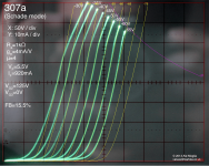
Comparing an older curve trace of "shunt Schade" with the "new" series Schade curves makes clear how much better the results are.
pics:
1) typical shunt Schade from Bartola's website (copyrighted): 307a with schade feedback (Part II) – Bartola(R) Valves
2) "new" series Schade
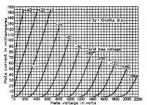
3) old style curves of 211 DHT tube
Attachments
Last edited:
Forgot to mention that the older "Shunt Schade" scheme depends on a linear V to I driver into a low impedance summing node. Tubes are not generally optimum drivers for this task.
You might also notice (requires a ruler) that the conventional "shunt Schade" scheme has some reverse roll-over in its curves. (really need a curve set over an extended plate V range to see it clearly) Caused by the inherent dist. in the R Fdbk, due to the drive V interfering, or non-linearity in the V to I driver stage.
You might also notice (requires a ruler) that the conventional "shunt Schade" scheme has some reverse roll-over in its curves. (really need a curve set over an extended plate V range to see it clearly) Caused by the inherent dist. in the R Fdbk, due to the drive V interfering, or non-linearity in the V to I driver stage.
Last edited:
Thank you smoking-amp for the detailed explanation, I was (and for sure still I am) missing alot of that new nfb system.
Can we say that the increase in power due to the contribution of the pMOSFET source follower is proportional to the local feedback we apply to the tube? The higher the feedback, the higher the grid voltage (if the divider is referenced to gnd), the higher the dc reference for the pMOSFET, the higher the power it dissipates, the higher the extra power it can deliver to the output transformer. DF is increased both by lower internal resistance and lighter loadlines (new working point is at an higher voltage with same current, so a lighter loadline can be used).
In PP amps it can increase the range at which the amp works in class A.
I saw your curves and Tubelab's ones always around 10% lnfb and g2 at fixed voltage.
Has g3 any effect on the triodeish curves (I remember the thread about the squared-up pentode curves)?
Last edited:
To echo zintolo, thank you for your explanation smoking-amp, very interesting topology you and tube-lab have cooked up, I will continue my reading and keep an eye on it as it develops further. Will be very curious to hear listening impressions of your first completed amplifier.
I have been given many good ideas on this thread, so I appreciate all of the feedback. I think the idea that has intrigued me most though is the 3C24 / 25T from SpreadSpectrum. This tube has been on my short list to use, I bought a small batch along with Eimac caps recently, but did not think to pair it with this transformer. The tubes themselves are still pretty cheap. I am putting together a prototyping board, so can breadboard a 3C24 amplifier when it is done.
Think I will keep the LL9202 primary wired as is at first and try a 400V 50mA bias point, only 80% of plate dissipation but these tubes get hot as hell anyway by the filaments alone! The 6.5K load will lower the amount of feedback needed, we'll see how it goes from there.
You said your curve tracer had difficulty with them. Is it just issues sourcing grid current?
Are you thinking something similar to your 801A amp? Any ideas for the input tube?
Are you thinking something similar to your 801A amp? Any ideas for the input tube?
You know, I wasn't sure of the issue at first but I came to learn every single 3C24 I have is gassy and won't conduct! Bought six of them untested dirt cheap, well seems that was a mistake 🙄 it is a common problem with 3C24, but I have a legit tested pair on the way, so should be able to trace the curves next week.
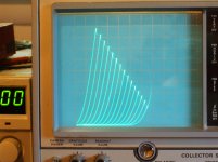
Fortunately, my NOS pair of HK54 traced no problem, here are the A2 curves for them. This tracer has two separate HV supplies, so you simply connect the second HV supply to the grid for A2.

Fortunately, my NOS pair of HK54 traced no problem, here are the A2 curves for them. This tracer has two separate HV supplies, so you simply connect the second HV supply to the grid for A2.
Last edited:
No conduction at all? They didn't hit a point where the gas would ionize and then they conduct a lot? (like a VR tube) Did any smoke come off the filament when you first lit them up?
I've tried cooking a few of these transmitter tubes to improve the vacuum and have had mixed success. Maybe some are salvageable.
I've tried cooking a few of these transmitter tubes to improve the vacuum and have had mixed success. Maybe some are salvageable.
At a certain voltage threshold, they will ionize and current spikes, somewhere around 3-400V. I've come across a few threads here where people cooked the tubes to degas, but sounds like a mixed bag, thought it better to just grab a tried and tested pair.
I've had some transmitter tubes that ionized at like 50-75V. Those cleared up very quickly and returned to normal easily. The gas cloud was blue and visible well outside the plate structure.
The ones that I've had that ionize at ~400V were more stubborn. The gas glow was inside the plate and very faint, more of a purple/pink color. I cooked one for 12 hours and it seems less gassy (the ionization event is now less abrupt). The metal on the plate structure looks a bit different now, like a bit of a patina has developed, I assume from absorbing gas molecules. I assume that if the gas hasn't cleared up in 12 hours, the chance of it clearing up is pretty small.
The ones that I've had that ionize at ~400V were more stubborn. The gas glow was inside the plate and very faint, more of a purple/pink color. I cooked one for 12 hours and it seems less gassy (the ionization event is now less abrupt). The metal on the plate structure looks a bit different now, like a bit of a patina has developed, I assume from absorbing gas molecules. I assume that if the gas hasn't cleared up in 12 hours, the chance of it clearing up is pretty small.
re: Zintolo
Yes, sounds like you have tuned into the idea (UnSET etc)
On the grid 3 effect, usually V on beam plates only has a minor effect for beamers (but can still be helpful in some cases, like fixing too sharp knees or knee hysteresis.) Pentodes with an actual grid 3 have enough effect to fix the knees, and dual control tubes have huge effects that completely re-design the tube.
I have recently found a half-way knee fix for the dual control 6888 tube that can give a large region of almost constant gm at higher currents, which could be interesting for class AB. However, it does not give the full gm and plate current boost for more power that a complete knee fix produces:
2nd pic:
https://www.diyaudio.com/forums/tubes-valves/356750-6888-tube-worth-messing-3.html#post6577033
Last edited:
What's the damping factor/distortion target for this amp? What are the resistances of the output transformer windings?
I'm just thinking about how much excess gain you will need for feedback...
I'm just thinking about how much excess gain you will need for feedback...
Thanks for thinking it over, I would be shooting for classic SET-esque targets in terms of DF and distortion, DF 3:1 at the least and an H2 dominant distortion spectrum. If I have extra gain to work with after hitting the DF target, might tune any additional feedback by ear.
Thank you again smoking-amp for further details you shared. Interesting tube indeed, I didn't know it, but I've found you talking about it in the "a better pentode for less" thread.
How tube's internal resistance can be calculated in this local a-g1 feedback configuration? And how can it be calculated in case of the Shade+UL configuration, as seen in other projects? I would like to know how to target a certain DF.
Thank you in advance for the time you dedicate to educate newbies.
If my back-of-envelope calculations are correct, you will need ~900 Ohm or less driving impedance on the primary of the OT to reach your DF target. Seems very doable with a little feedback.
Edit: An A2 CED/UNSET approach would be really cool but I don't think the 3C24 has enough gm to reach your DF target with a practical amount of feedback. It looks like it would take ~50%, which complicates things...
Edit: An A2 CED/UNSET approach would be really cool but I don't think the 3C24 has enough gm to reach your DF target with a practical amount of feedback. It looks like it would take ~50%, which complicates things...
Last edited:
Yeah seems doable! Similar to my 801A amp, think I would use a grid-biased DC coupled cathode follower to fine-tune the 3C24 bias, maybe 6AH4. I was recently shown a 3C24 schematic with a 5K load, used plate-to-plate local feedback on a resistively loaded EF86, so it can be done.
Load line maybe like below, 400V 60mA 6.5K. Practically speaking, I would need some sort of ventilated enclosure for the 3C24. There is a plastics shop near me that does custom work, I wonder how polycarbonate would hold up.

I might leave the UNSET / CED to the trailblazers 😀 I am still living in the 1990s tube DIY era, trying to catch up. Should have some functional 3C24 tomorrow, will trace some curves.
Load line maybe like below, 400V 60mA 6.5K. Practically speaking, I would need some sort of ventilated enclosure for the 3C24. There is a plastics shop near me that does custom work, I wonder how polycarbonate would hold up.
I might leave the UNSET / CED to the trailblazers 😀 I am still living in the 1990s tube DIY era, trying to catch up. Should have some functional 3C24 tomorrow, will trace some curves.

- Home
- Amplifiers
- Tubes / Valves
- Single Ended Output Tube for Lundahl LL9202 50mA