Mark....thanks I honestly did not see the R3 - R6 resistors in the schematic!! and I never noticed then missing when I compared my board to your good pix!!
OMG..so embarrased!! Just popped them in!! Gosh being 69 yrs is taking its toll here!
:>)
Alex
OMG..so embarrased!! Just popped them in!! Gosh being 69 yrs is taking its toll here!
:>)
Alex
Note the 28 ga silicon wire AGDR mentioned came in today and the insulation is too thick to get 11 turns in the ferrite bead..I got 6 and could not get any more thru.
So I have some 24 ga enet cables I am trying right now.
Alex
So I have some 24 ga enet cables I am trying right now.
Alex
I got 12 loops with the 24ga enet wire!!
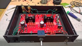
Case is here, holes drilled...wiring it up now....sty tuned.
Alex
Case is here, holes drilled...wiring it up now....sty tuned.
Alex
I don't have time to do a long post with a ton of photos, that will happen in a few days when I get back from a trip...
Those that know me and have read things that I write about the different amps and projects know that I rarely, if ever, talk about sound quality and sonic differences.
I will say this - T2 is absolutely amazing. I believe it to be the best HPA I've ever heard.
Those that know me and have read things that I write about the different amps and projects know that I rarely, if ever, talk about sound quality and sonic differences.
I will say this - T2 is absolutely amazing. I believe it to be the best HPA I've ever heard.
Its Alive!!!
It works....fist time...Yahoo!!
Adjusted to 5.1 vdc..and the LED.
Its really "GOOD"...
I will do a further listening review and evaluation.
Have to run to the store for some more metric bolts!
Alex
:>)
It works....fist time...Yahoo!!
Adjusted to 5.1 vdc..and the LED.
Its really "GOOD"...
I will do a further listening review and evaluation.
Have to run to the store for some more metric bolts!
Alex
:>)
In the case...
Had to do some DIY here....with the screws and mounting standoffs for the board. I found black 5-10mm allen cap bolts at LOWES 2 for 98 Cents! When I get a knob for this I will post a few more pix.
I am listening with the amp driven by a Schitt Bifrost Multibit dac....the sound is silly crazy good...I am gushing all over the place here its that good..
Its like a very wide open , spacious, clear, crisp presentation...the first time I had am amplifier sound like I got a new set of headphones...there is Mark Johnson magic in this amp.
I agre with 6L6....its the best amp I have heard to date and I have heard a lot of them....(i have 10 in house at the moment)...
Using Beyer T1a second gen version and I was thinking of selling then because they were becoming "dull" sounding...not anymore...the pairing here has brought the best out
of them....its like holy cow what happened....
The live music I have, folks on stage etc have come the closest to being there than anything I have heard before.
I was not expecting much from this simple design and am blown away at how well it performs...
If your looking for a easy DIY project that will blow your socks off this is it.
Run dont walk and contact Mark for the pcb and panels ...the BOM makes ordering easy peazy....
Back to listening!
Alex
Attachments
Last edited:
Thanks so much for a very nice review!
I have edited post #1, adding a little section of pointers to reviews of T2. If more listening evaluations and reviews begin to appear, I'll include them in the list. Embedding the list within post #1 makes it a bit easier to find, particularly for people visiting the thread for the first time.
The PMs I have been receiving, suggest that a few T2 builders are eager to hot-rod their boards in some way. Why just build it when you can OVERBUILD it, or something. I've attached a pdf containing three of the least dangerous tweaks that spring to mind. In my opinion they are unnecessary but probably harmless. And by unnecessary, I mean that I haven't done any of them to any of the T2s which I've built myself. But for those who cannot be happy with their BMW until they've installed racing tires and a "performance chip" modification of the engine control computer, here are some unnecessary mods you might think about performing upon your T2 headphone amp. And may God have mercy upon your soul.
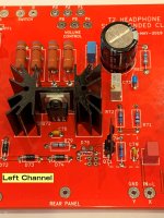
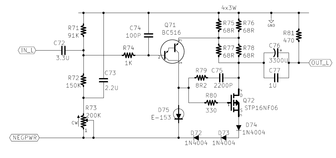
Also attached are a couple of photos that didn't seem to fit in earlier posts. One is the resistor elevator pencil trick as performed by Beta Tester #1. The other is a cropped picture showing one channel of T2 amplification. This picture emphasizes that T2 is a very simple circuit with very few parts.
edit- what about the third photo? Whazzat? It's an example of what you might see if you attempt unnecessary modification #2. I've never done this myself but Wildman the Beta Tester sure did.
_
I have edited post #1, adding a little section of pointers to reviews of T2. If more listening evaluations and reviews begin to appear, I'll include them in the list. Embedding the list within post #1 makes it a bit easier to find, particularly for people visiting the thread for the first time.
The PMs I have been receiving, suggest that a few T2 builders are eager to hot-rod their boards in some way. Why just build it when you can OVERBUILD it, or something. I've attached a pdf containing three of the least dangerous tweaks that spring to mind. In my opinion they are unnecessary but probably harmless. And by unnecessary, I mean that I haven't done any of them to any of the T2s which I've built myself. But for those who cannot be happy with their BMW until they've installed racing tires and a "performance chip" modification of the engine control computer, here are some unnecessary mods you might think about performing upon your T2 headphone amp. And may God have mercy upon your soul.
Also attached are a couple of photos that didn't seem to fit in earlier posts. One is the resistor elevator pencil trick as performed by Beta Tester #1. The other is a cropped picture showing one channel of T2 amplification. This picture emphasizes that T2 is a very simple circuit with very few parts.
edit- what about the third photo? Whazzat? It's an example of what you might see if you attempt unnecessary modification #2. I've never done this myself but Wildman the Beta Tester sure did.
_
Attachments

Last edited:
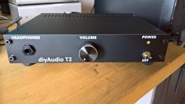
One thing I have noticed since the knob went on this morning is where it is set when I listen with my 600 ohm T1's...for a really nice presentation and lively level its at 12 noon position, right in the middle of the pots mecahnical travel....didnt notice this when I was grabbing the pots shaft and turning it..so this to me is ideal with the gain as is the volume is in the middle and I like that..its not anyway near the beginning of the travel and away from any channle imbalance issues.
The only thing I would like to see, maybe is a anti-thump turn on off relay in the cuircuit.
But not if its going to upset or change the sonic attributes in any way.....its easy to turn down the volume and unplug the headphones etc before powering off.
I will say again..this amp is a real winner here, its a stellar performer...its so dang clean and clear and transparent...
I have had Class A amps before and do have a 2 watt Burson FUN amp with their discrete op amps....an order of magnitude of parts to achieve what the T2 does with 2 transistors!! ...
I havent gone back and forth with these two amps for a honest side by side but will soon.
Great Job Mark!
Alex
Builders may not notice at first glance, that the LED specified in the Mouser BOM and Mouser shopping cart (here it is) ...
is actually a bidirectional LED. Apply power one way and it glows yellow. Reverse it, connect power the other way and it glows green.
This means that the LED will glow when power is applied, no matter which way you hooked it up. You can't connect it "wrong" because it works either way.
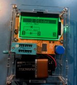
Insert this LED into your Mega328 tester and run a test. Notice that it glows both colors during testing. Observe the cool and unusual output device schematic on the Mega328 screen. That's a whole lot of fun for only $0.36.
is actually a bidirectional LED. Apply power one way and it glows yellow. Reverse it, connect power the other way and it glows green.
This means that the LED will glow when power is applied, no matter which way you hooked it up. You can't connect it "wrong" because it works either way.
Insert this LED into your Mega328 tester and run a test. Notice that it glows both colors during testing. Observe the cool and unusual output device schematic on the Mega328 screen. That's a whole lot of fun for only $0.36.
Builders may not notice at first glance, that the LED specified in the Mouser BOM and Mouser shopping cart (here it is) ...
Yes, I saw that 6L6 had put this led in the BOM although I didn´t know exactly what purpose.
I'm tempted to beef this circuit a bit to drive some little ND25FN tweeters. Too bad they don't make a 16 ohm version.
You could extract the plot from post #2 and then draw by hand the "16 ohm" curve on the plot. How does it compare to the "T2 is just about to enter clipping" curve in blue?
Here is the T2 front panel LED test result on a Mega328. It has correctly discovered that there are TWO light emitting diodes in the package.
I recommend all builders of diyAudio equipment obtain a Mega328, it is an incredibly useful piece of super low cost gear (link)
_
I recommend all builders of diyAudio equipment obtain a Mega328, it is an incredibly useful piece of super low cost gear (link)
_
Attachments
This is a nice amp design, and I am glad that folks are trying it as they will discover the wonderful world of simple SE ended Class A headphone amps that sounds so good. Just a couple of clarifications to reduce confusion by readers/builders of this amp who may go on trying to build this amp by looking at only the schematic. I was looking up P channel MOSFETs based on the schematic diagram symbol, but it's really an N-channel.
The schematic diagram shows a P-channel MOSFET, but the part number is an N-channel, and your description says N-channel. The arrow on the symbol should point into the die-pad, not away as shown. This is the second time one your schematics shows an incorrect symbol for an N-channel MOSFET, other time was in the M2X schematic here (both N and P channel symbols were flipped):
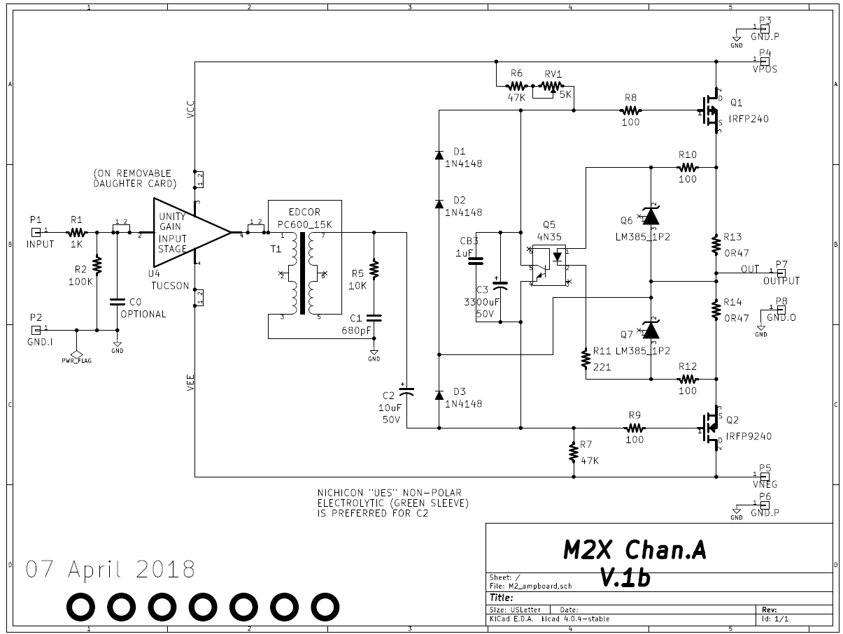
It would seem that your schematic software/sim software (KiCad?) might have the symbol notation reversed.
Here is what it should look like:
Second clarification is that a Darlington transistor is actually two (2) transistors conveniently bound together on a single die with 3 pins. So technically, this is a 3-transistor HPA, or maybe a T3?
The schematic diagram shows a P-channel MOSFET, but the part number is an N-channel, and your description says N-channel. The arrow on the symbol should point into the die-pad, not away as shown. This is the second time one your schematics shows an incorrect symbol for an N-channel MOSFET, other time was in the M2X schematic here (both N and P channel symbols were flipped):
It would seem that your schematic software/sim software (KiCad?) might have the symbol notation reversed.
Here is what it should look like:
An externally hosted image should be here but it was not working when we last tested it.
Second clarification is that a Darlington transistor is actually two (2) transistors conveniently bound together on a single die with 3 pins. So technically, this is a 3-transistor HPA, or maybe a T3?
Last edited:
Hi, did you happen to see these remarks in post #1?
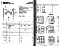
The semiconductor process description page calls the PNP input transistor a "monolithic" (all devices built in the same substrate) darlington, attachment below. You can see it has only two bondpads, one for base and one for emitter. The backside die attach (substrate) is the collector. The connections between the small input PNP and the large output PNP, are not made with bondwires spanning two separate die. They're monolithic.
I'm not too worried about builders accidentally purchasing and installing the wrong polarity MOSFET, since the circuit description in post#1 states the device polarity (N-channel) again and again, and it goes on to explain why N-channel was chosen, in detail. The MOSFET part number on the schematic, matches the part number on the Excel spreadsheet BOM in post#1, which also matches the part number in the shared Mouser shopping cart in post#5. They all say "STP16NF06" which is correct. It's an N-channel power MOSFET.
I've heard back from several builders who bought the whole Mouser shopping cart and successfully built a working T2 from those parts. The procedure is working smoothly, at least so far. Nobody has accidentally purchased a P-channel MOSFET that I'm aware of.
So I think I'll leave the schematics as they are, despite your concerns. Thanks for sharing your thoughts!
Best,
Mark Johnson
_
Some may not agree that the T2 circuit can be called a two transistor amplifier. For one thing, darlington "transistor" Q71 is, in reality, an integrated circuit with two transistors on the same die. And for another, it feels like cheating to call D75 a diode and not a transistor. Even though D75 has only two terminals, even though it cannot provide voltage gain, current gain, or power gain, D75 just seems like it needs to be called a transistor. To those who feel this way, I gently reply: you may be right. However I really like the name T2 and I plan to keep using it. Feel free to call it by another name (T2++ ??) if you prefer.
The semiconductor process description page calls the PNP input transistor a "monolithic" (all devices built in the same substrate) darlington, attachment below. You can see it has only two bondpads, one for base and one for emitter. The backside die attach (substrate) is the collector. The connections between the small input PNP and the large output PNP, are not made with bondwires spanning two separate die. They're monolithic.
I'm not too worried about builders accidentally purchasing and installing the wrong polarity MOSFET, since the circuit description in post#1 states the device polarity (N-channel) again and again, and it goes on to explain why N-channel was chosen, in detail. The MOSFET part number on the schematic, matches the part number on the Excel spreadsheet BOM in post#1, which also matches the part number in the shared Mouser shopping cart in post#5. They all say "STP16NF06" which is correct. It's an N-channel power MOSFET.
I've heard back from several builders who bought the whole Mouser shopping cart and successfully built a working T2 from those parts. The procedure is working smoothly, at least so far. Nobody has accidentally purchased a P-channel MOSFET that I'm aware of.
So I think I'll leave the schematics as they are, despite your concerns. Thanks for sharing your thoughts!
Best,
Mark Johnson
_
Attachments
I'll leave the schematics as they are
Sure, it's your thread. My opinion is that schematics should be self-standing and complete without notes contained elsewhere, and critical notes, like P or N channel (if not using conventional terminology/symbols) should be spelled out on the part next to it or in footnote section of schematic.
Always a critic...not a poet!!
It never bothered me at all....🙂
Ordered parts from the BOM, inserted in board (this is where it really counts!!) and as long as the part I ordered is the correct one and fits in the board correctly alls good.
The amp worked first time and I am so exticted that is really that good!
Again ..
Great Job Mark making this a really easy, awesome performing amp!
Decided to order a board and give this amp a shot.
Looking at parts now, and some thoughts
10k pot is on backorder from pl is on backorder, but 67YR10KLFTB is in stock, only difference is packaging.
Standoff is M3, metric. I plan to use 4-40 standoffs because I have lots of 4-40 hardware around, but very little metric.
I thought I had a suitable transformer in my junk drawer, but on closer inspection it was a 24 VAC output, so NOT ok to use. US sprinklers use 24VAC, which is why I have it. Will take another look tonight, otherwise will use the one from Mouser BOM.
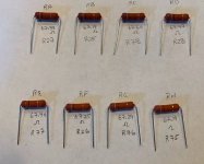
Thinking about trying alternate coupling output coupling caps. Don't want to restart caps vs no caps debate, IMHO its pointless. But I think there could be a benefit to trying alternate output caps. I've used Panny organic polymors in another head amp and liked them, so thinking about ordering them too.
Randy
Looking at parts now, and some thoughts
10k pot is on backorder from pl is on backorder, but 67YR10KLFTB is in stock, only difference is packaging.
Standoff is M3, metric. I plan to use 4-40 standoffs because I have lots of 4-40 hardware around, but very little metric.
I thought I had a suitable transformer in my junk drawer, but on closer inspection it was a 24 VAC output, so NOT ok to use. US sprinklers use 24VAC, which is why I have it. Will take another look tonight, otherwise will use the one from Mouser BOM.
Thinking about trying alternate coupling output coupling caps. Don't want to restart caps vs no caps debate, IMHO its pointless. But I think there could be a benefit to trying alternate output caps. I've used Panny organic polymors in another head amp and liked them, so thinking about ordering them too.
Randy

- Status
- Not open for further replies.
- Home
- Amplifiers
- Headphone Systems
- Single ended class-A headphone amp using two transistors: T2