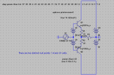
The null point is between full class A and class AB. For a bipolar EF the first AB point doesn't cancel completely, but if you keep going up you'll get to another point that cancels better... It is very easy to miss. I think this same behavior would show up if you added together two exponential curves (one inverted along the Y axis) and varied the Y intercept.
If want a good mix between A and AB, I say the null point is the way to go. the first watt will be class A, and the rest will distort minimally.
I've attached a demonstrative file for the Null point. The two null points, for class AB and for Olliver's, are at .61V bias and 1.4V bias. Rename .txt to .asc.
- keantoken
Attachments
Last edited:
BJTs are log law. They might have a narrow sweet spot, or at least a minimally bitter
one. But its gonna vary substantially with temperature, especially if curving function
is decided by a power dissipating device. Slightly surprised, but not totally shocked
to hear that these curves might blend in two places rather than one... I'm not sold
that entire theory just yet, but it sounds a strong ring of plausibility.
I think with Schottky, you find a closer approximation of quasi-complimentary square
laws, and a much wider AB sweet spot for smooth crossing. The decision maker need
not be, and should not be: a power dissipating device, drifting with waste heat. You
can Schottky several inches away from the worst of the burning smell.
You also conveniently ignore that series resistors straighten up either flavor of curve,
and this could modify your bias point of smoothest crossing. You also ignore that with
any diode that recovers quietly, you could add a simultaneous do-nothing current to
keep the power devices always-on. And that current too probably modifies the ideal
crossing, especially if the power device retains control as the primary curve bender....
I think we need to get entirely away from power devices as primary curve benders...
The circuit above's simulated ideal crossing point(s) are irrelevant, because any real
junction temps would be wobbling all over the place...
Last edited:
I was aware that the null point varies strongly with temperature. However with the Allison, the diodes don't dissipate most of the power. I'm not yet sure of any practical developments.
- keantoken
- keantoken
You totally good with Allison + Schottkys. No decision is made by power devices...
And the BJT's that must perform the error correction comparison are essentially at
constant current, well above the worst of thier own curve. Assuming you have a
do-nothing-current in parallel with the Schottkys, as previously described. To keep
power devices minimally-on, and decision making devices biased above the curve.
Its mostly emitter follower AB (as you show above) I got issue with... Just not a
good example of anything, except how to cross thermally unpredictable curves
in a way that won't blend well except by random chance.
Last edited:
It is interesting looking into this. Using silicon diodes MUR460, Null was found at 779mA as opposed to 1.37A. The tempco wasn't as sharp either. If the null point is found at 25C, then it jumps up to about .00425% at 20C and 30C. Two 745's in series had better tempco, with .001% tolerance between 20C and 30C, bias of 1.193A.
So it seems to me that most diodes cancel fine, it's more a matter of temperature management. Also, LTSpice simulates all devices at the given temperature parameter, so for these simulations, output diodes and Allison transistors were effectively thermally coupled.
IIRC, series resistors disrupt this null point. I will have to see.
- keantoken
I don't know if silicon junction diodes can recover fast enough for really clean AB???
Schottkys certainly can. Well, almost any majority carrier diode shutoff could be
cleaner than tryin to suck out leftover minority carriers from a Power BJT's base.
Am I making a wrong assumption here about which junction cleanup is slower?
If you use MOSFETs, to avoid pointlessly depleting threshold charge from the gate
you must later replace to turn it back on, might be good reason to want to keep
those types of transistors out of cut-off too. So, the same circuit applies. We let
crossing diodes do the AB dirty work of shutting down...
Regardless what type power device is slaved to the curves of the crossing diodes,
you almost certainly want to add a small reserve ON-current through the power
devices.
Your diodes can insure that neither a reactive load, nor bootstraps, can source or
sink away any of that reserve current. Only the power devices themselves can flow
this current after the diode has shut off, thus they are tricked to always stay on.
You've seen me do this before. Throw a resistor across the voltage gap, that has
no obvious connection to the load... This hack works great, except in clipping.
Then I'm wishing the reserve current loads were CCS to the opposing rail instead...
I'm not feelin how a silicon junction diode could compete with a Schottky here???
Slower, noisier recovery, wastes more heat and voltage drop, so WHY??? If you
really just need the voltage drop to match an emitter, two Schottky in series will
do that.
Last edited:
This is DFenriz inspired input stage. I thought it looked to me kinda like Allison?
But turned backward of the way we usually do, his emitters connected to load...
Unlike Fenriz, I connect the node between Q2 Q3 emitters to GND. So, in this
configuration, we have an inverting amp.
Anyways, what I show with the Schottkys and the reserve current bypass are
exactly the same what I would do with any "normal" Allison, and for the same
reasons.
You can see I've abandoned my usual 0.1R in series with one Schottky in the
output gap. This last vestige of Class-A resistively crossed Allison is gone.
Square law crossing is still plenty smooth, even though deliberate underbias of
two Schottkys here creates a very small, almost Class B crossing, its glitchless!
And remember: I got another 120mA+ shootin thru R12, so my power devices
are never actually sufferin' class B. Its only the Schottkys what ever turn off
and/or forced to operate on the curve.
Pick-a-bias, any reasonable bias, a square law will cross it. Thats why I don't
have to worry or maintain what is exact bias for square law "Null" ???? It just
don't matter that much when your diode got the magic curve..
Attachments
Last edited:
I keep forgetting that resistor, but I'm fully aware of its function.
KenPeter, I'm not sure why you say the null point doesn't matter. Distortion goes below .001%. I think it's at least worth investigating. This is with the same schottkeys with that magic curve... If you open the EF file I attached and look at the error log, you'll see that the distance from a null point can make a few orders of magnitude of difference of distortion.
The schematic does seem to have the same basic idea. Replace the diodes with resistors and you'll have a very low distortion class A stage, with high impedance input. The high impedance input here makes it a good bench amp IMO.
- keantoken
Last edited:
Not sure how I'd make it stable. How much parallel capacitance do those zeners have? Have you tried putting a resistor in series with them?
- keantoken
- keantoken
Sim busts into brief random oscillations with or without Zeniers and/or Current limiters.
Doesn't seem to matter what in/out comparator up front, always the same symptom...
I don't think it helps that I wrap CDOM around the component that defines clipping.
I need to define clipping level thresholds up front somewhere, so that errors don't
get stored in the CDOM. Sticking to the rail after clip and all that nonsense... Back
to back pair of 4.7 Zeniers to GND at input emitters is helpful, but doesn't quite fix
everything.
Schottkys across the comparator, surprise to me, don't seem to clip output Voltage.
Instead, they seem to clip the slew rate. I don't got my mind fully wrapped around
how the phase of that style pre-clip got shifted 90deg??? Maybe need to ditch C1?
Last edited:
An alternative is to reference Cdoms at the junction of Q5 and Q6.
Why not try adding local feedback to Q5 and Q6, like the way we traditionally compensate the Allison? Gate resistors on the MOSFETs would strengthen this compensation by adding significant HF impedance to the gate capacitances.
Also, with the current diode biasing I'm sure there is crossover distortion. Probe at Q5/6 emitters and you will see. HF spurs like this tend to aggravate resonances, which can become oscillations (also, try increasing your timestep to a very small value and then see how the oscillation changes - circuits often oscillate sooner when you increase the timestep, due to aliasing and frequency implications of sample times). And just to note, I don't like crossover distortion one bit because the crossover point is very, very hard for an amp to compensate for, and at high frequencies can saturate the compensation (this will be more significant for high-OLG amps), resulting in 20KHz THD death. During this spike the output stage's own gain becomes unreliable, making delicate control impossible for the amplifier.
- keantoken
Last edited:
Local feedback between the emitters of Q5Q6 throws it into worse oscillation.
There is NO significant crossover distortion, believe it or nutz... Like Visch B.
A drop in the bucket of overall THD, which is always my last/least concern
after shaping every other misbehavior one might actually hear. I havn't tried
CDOM on Q5Q6 yet, get back to you on that...
In the meanwhile, chew on this one? I think I got it mostly stable, and upped
BW to at least 96K with only a little rolloff... Clipping is controlled up front, so's
not to store a charge on CDOM. Nor get in a situation where an opposing gate
is finally overdriven into complete cutoff. The cap I added is a bit of a problem
that it tries to shut off the opposite gate in spite of everything, so it needs to
keep some resistance in series.
I had to bump up the power rails, since I didn't have an appropriate Zenier
threshold to clip just below the old 50V rail. I suppose I coulda changed the
gain instead of moving the rail up 5V, but I opted for rail cheat... Whatever...
Why no default Zenier models lower than 4.7, nor between 4.7 and 6.2?
I didn't feel like drawing a big twin stack of Schottkys, which woulda been
the ideal soft pre-clip solution (for fastest recovery) except the parts count.
Attachments
Last edited:
If I knew anything bout programmin DSP's, I'd see what happens when you
soft clip only the lowest/biggest root note by adding or subtracting musically
relevant harmonics to it. Leaving the rest of the music untouched by IMD.
Like the offending clipped tones each had its own independant MI amplifier.
If you notice, rail clipping and slew rate clipping stop the waveform cold.
Information is irreplaceably lost. Even if you somehow filter off the nasty
IMD sidebands, you are missing something that used to be there. Maybe
synthetic music and MP3 music clipping loss is predictable and replaceable?
Hard clipped real music and voices, loss is loss... So lets not clip what we
don't have to, and no harder than necessary.
Transients is transients, with no spectrum of relevant harmonics you could
easily separate from the rest of the mix. If transients clip, they clip. I don't
have a DSP plan for this yet, cept recover real fast, hope nobody noticed...
The alternative is pre-emptive compression, but I worry you could worse
hear compression breathing as it anticipates and recovers around a spike.
Such a transient has no information but amplitude and width. A soft clipped
transient doesn't seem any worse to me in that respect than a compressed
one. And probably does less damage to the music around it.
Last edited:
I've thought about that too. My implementation would be to put swing limiting in the feedback loop, with some AC filtering. Voltage clipping would stop waveforms totally but current clipping would only clip bass frequencies.
In my previous schematics there was bad crossover distortion with this diode configuration, which is puzzling. The Allison transistors also have a bias of over 10mA, which gives you several mV more bias than I was running.
- keantoken
In my previous schematics there was bad crossover distortion with this diode configuration, which is puzzling. The Allison transistors also have a bias of over 10mA, which gives you several mV more bias than I was running.
- keantoken
Current clipping can be hard clipping too. Any time the slope becomes a straight line...
Informations about higher/smaller frequencies is lost for the duration. IMD spectrum
may still contain ghosts of those lost frequencies, but they contain only information
from the part of the duty cycle that was not in clipping. What lost information was
present in the original signal? Your mind and ear can only guess.
If you don't clip it all the way, and all at once, maybe you can guess better???
If some information is made smaller at the extreme peaks and slopes, this is still
theoretically reversible damage. But once you hit a straight line, its gone...
Last edited:
The Allison transistors also have a bias of over 10mA, which gives you several mV more bias than I was running.
Where? I measure only 1mA in Q1-Q4, 7.3mA in Q7-Q10, 8.4mA in Q5-Q6.
Only current mirrors and output totem have quiescent bias above 10mA.
Also, with the current diode biasing I'm sure there is crossover distortion.
As for terrible horrible diode crossover distortion... This is 1W into 8ohms at 1KHz.
The Schottkys cross about 350mA, the MOSFETs cross about 450mA due to the
100mA always-on reserve current that bypasses both the Schottkys and the load.
I did create a 96KHz dummy loop to trick LTSpice to compute an FFT this smooth.
It wouldn't have looked this clean if it took all the math shortcuts it normally does.
Attachments
Last edited:
That distortion is taken down by the feedback of the frontend. I won't deny it, things are working very well here.
It looks like a nice amp to me. Is it stable now that you've made an FFT?
And there are other ways to turn off LTSpice's default compression. See the link in my signature.
- keantoken
It looks like a nice amp to me. Is it stable now that you've made an FFT?
And there are other ways to turn off LTSpice's default compression. See the link in my signature.
- keantoken
Last edited:
Distortion slightly worse, but stability now way way up....
That cross couple comped version was faster, but fights
against Q5 Q6 absolute control of the crossing and never
quite "unconditional" enough to satisfy. It had to go.
I moved CDOMs around several places before deciding this
placement offered the most benefit for least side effects.
And like before, I'm finding a small series resistor along with
CDOM heps the phase not roll too quickly. After all, there is
always some other parasitic phase shift, even if you are far
from the other pole(s).
I'll post up the drawing later. Almost buildable at this point.
I don't have 55V power supplies, so I need to modify a few
things (like the pre-clip) to work better with 24V rails.
Attachments
- Home
- Amplifiers
- Solid State
- Simulation Analysis of several unique Allison-based output stages.