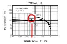
On the 4793 datasheet, Hfe crests at around 60mA... This would be the optimal bias point, but that's a little hot and the device is so linear I don't think it matters that much anyways. What's most important is that the device has enough bias current that it won't turn off on current spikes. I'm pretty sure 500 ohms is fine here.
- keantoken
keantoken,
If I wanted to look at the current for this transistor in the simulation, should the current be determined with zero volts input? Am I correct that by placing the cursor over the transistor, having the cursor change to the amp meter at the transistor base it give me the current that is used for looking at the Hfe graph?
Ken L
Attachments
No.
Beta or Hfe is current gain, taken from the input/base, to the output/collector. So plot Ic/Ib. And then you will have the value in the graph. Keep in mind, the model might not be exactly like the real device, and even then real devices can vary widely.
- keantoken
Beta or Hfe is current gain, taken from the input/base, to the output/collector. So plot Ic/Ib. And then you will have the value in the graph. Keep in mind, the model might not be exactly like the real device, and even then real devices can vary widely.
- keantoken
Regarding V6, in the simulator it has a THD sweet spot where THD is roughly even regardless of power level, at around 100mA bias. (you might also try the capacitor tweak from the above paragraph, but I haven't mentioned it thus far because I did't expect it to have an affect - I'm realizing now that it may affect stability for better or for worse)
Again I thank you for your tests,
- keantoken
Where are you measuring 100mA, I get 5.6A between the emitters of the output tansistors... about 1.010v input shorted.
Never wanting to rely on just one test, I hooked the V7 up again and place the wires in the same configuration as the Allison test last night. What do you know, it ran great. I spoke to soon about giving up on it. A bit more low level harmonics than the standard Allison, but otherwise, quite clean. Now what to do?
Ken L
Attachments

5A, that's pretty high... Weren't you trying to run "cool"? I measured 100mA through the output diodes, but the simulator lets you measure weird things like that... If you can't directly measure the bias current, try putting .1 ohm resistors in series with the output collectors.
Probably the reason 100mA is the "sweet spot" is because this is usually around the optimum class AB bias point for a darlington EF. So this means that the Allison is working less hard.
My thoughts on the matter are that V6 is more foolproof and has been shown to be stable in the simulator, while the bootstrapped one has spooked the jury. Also, the bootstraps make the Allison less effective, and it gets worse the lower the frequency, depending on the caps you use.
To my great dismay, it's disturbingly hard to give a circuit due process in real life simply because too many things can go wrong... Bad connections, alligator clips, etc. It takes some experience to really get this right I think.
- keantoken
It's running a bit warm, I have the resistors between the allisons at a total of 200 ohms, should be more like 170 to 180. I didn't have 85 or 90 ohm resistors handy. I'm also using .1 for the Re's .2 might be a bit better. Regarding the V7 it's oscillates without a load, when loaded it's stable. I'm going to try bumping up the compensation caps a bit from the current 51pf to see if this solves the oscillation.
Ken L
Ken L
Improvements to V7
It was a good day 😀 .
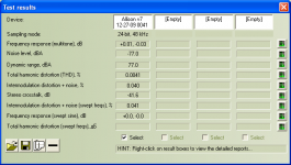
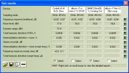
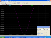
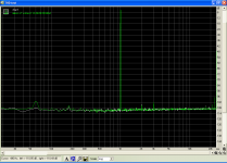
I added 1,000uf caps on the board at the supply rails to calm the low harmonics and it seemed to work. Then I spent some time with the LME49811. My v2 of it measures .001 better than v1, but when hooked up to the Allison V7 didn't do as well, harmonics at 2k and 3k. Started swapping stuff out and found that the 30pf comp cap was not as good as 33pf on v1 - who would guess that 3pf would make a difference, or maybe because it's of a different manufacturer. So went with the 33pf and the harmonics went away. Noise base is now below -108db and still tracking with any improvements to the LME49811. It now measures better than the CFP stage. The results page show the CFP in the far left column and three test of V7 in the remaining columns. Thd plot is of the 3rd from left column.
Ken L
It was a good day 😀 .
I added 1,000uf caps on the board at the supply rails to calm the low harmonics and it seemed to work. Then I spent some time with the LME49811. My v2 of it measures .001 better than v1, but when hooked up to the Allison V7 didn't do as well, harmonics at 2k and 3k. Started swapping stuff out and found that the 30pf comp cap was not as good as 33pf on v1 - who would guess that 3pf would make a difference, or maybe because it's of a different manufacturer. So went with the 33pf and the harmonics went away. Noise base is now below -108db and still tracking with any improvements to the LME49811. It now measures better than the CFP stage. The results page show the CFP in the far left column and three test of V7 in the remaining columns. Thd plot is of the 3rd from left column.
Ken L

Hey, K3! (stunning, we 3 K's have been the only ones here for some time - K theory, anyone?)
Or are you K1? Maybe K2? Hmmm, not sure...
Maybe the old 30p's were bad types, because certain ceramics are highly nonlinear. Then again, that would be low-level compared to the distortion the diodes do...
And it seems you forgot to post the charts, though I'm sure you'll get to it in a few secs.
- keantoken
And, you may want to take special notice of this:
Since the output devices' AC characteristics and frequency response, etc. change with current, so will the feedback characteristics - so at 0V it may be stable, but once one device shuts off and the other is in mid swing it will start oscillating, then shut off when the other device kicks in. So a few extra pF of compensation shouldn't hurt. It can be a bad idea to give "only as much" compensation.
It's getting better, .001%THD at a time...
- keantoken
Last edited:
I thought I would continue the discussion regarding currents through the driver and output on the allison here. So, I ran the simulation of V6 with a 2r0 load, to test the extremes. Andrew suggests currents for reactive loads could be up to 3x of what you might see with a fixed load. And it's only a simulation...
From the prior post in the other simulation thread, I found that the pnp drivers carried the bigger load, so, looking at them with a 2r0 load we get about 202ma current. Looks like that's within the SOA of the device. The single outputs are may be cooked at 13.49A. Though at 30v Vce, they are right at the ragged edge, a bit hard to tell with the log SOA chart.
Ken
Attachments

I've just realized what should have been, for me, and obvious advantage to NOT driving the Allison through the emitters.
When you drive it through the emitters, all the driver current goes through the Allison Q's and injects harmonics into the feedback loop. But with source/sink drive, the Allison only contends with common mode currents... So theoretically, the current configuration should work better than emitter drive.
- keantoken
keantokenI've just realized what should have been, for me, and obvious advantage to NOT driving the Allison through the emitters.
When you drive it through the emitters, all the driver current goes through the Allison Q's and injects harmonics into the feedback loop. But with source/sink drive, the Allison only contends with common mode currents... So theoretically, the current configuration should work better than emitter drive.
- keantoken
I had also been looking at the sims to make a clean current source instead of the bootstrap and kept finding sign ificantly higher thd number. So I just finished a cleaned up version 6. But, it's currently oscilating. Every time I try a faster driver, I seem to get oscillations. This too will be solved.
KenL
V6a up and running. Source Sink configuration, 15032/33 drivers 100pf compensation, no oscillation. I think I can reduce the compensation, but, I don't know if it makes any difference in the amp's performance. Best results so far of all test, now the improvements are coming at 1/10,000th at a time 😛 Again, I'm up against the noise floor of the LME49811. The 60hz harmonic that I believe was from the bootstrap drive is gone. Still waiting for new sound card to arrive for high power tests. These are done with -24db input.
The interesting thing is the simulation runs best on the 2SC4793/1837 driver pair(these are the _x models), but, the real device won't run on something that fast. So, is it the low Cob of the 2sc4793 or speed or combination of both that causes the real world problem? And why do the slower devices oscillate in simulation? What part of the model is the cause?
KenL
Attachments


OK. I got sim problem with this one, maybe real problems too? I don't know.
If it works, this has the lowest distortion of any circuit EVER, just maybe...
Theory of operation:
Allison corrects output drops to match input drops. What might be at any
current they so please, whatever drive the output transistors may wish.
This voltage reference is flawed. Because drive currents are not steady,
and they must flow directly through the comparator junctions.
Tallison actively corrects input collector currents to match a reference.
Results in input emitters with a nearly fixed currents and voltage drops.
And outputs merely swing to make the input emitter voltage and current
be steady. This is sorta similar what happens in Taylor or White Cathode
Follower.
Now we got Emitter distortion out the way, cascodes can get rid of Early.
And what we have left is a pair of offset followers with near perfect refs.
For error corrections that do not vary substantially with output or drive.
Distortion unbelievably low when sim occasionally decides to cooperate.
-----------
But I can't make the sim to be stable. Even dumbed out the bootstraps
to LT's CCS to see if that was it? Nope... It works great as posted, but
change the frequency, amplitude, or sample rate: It goes straight into
wild oscillations.
What can be done to fix this schematic and/or the sim parameters?
Attachments
I'm thinking it's more the circuit than the simulation parameters.
Aha, try this. Large dopey Cdom's work well. 1KHz distortion is the same, 10kHz suffers a bit, but I'm sure that's a price well paid - distortion is below .002% with a 10k source impedance - at 10KHz, 10V pk-pk.
Pretty amazing, for only BJT's (but is it worth the reduced price of similar performing MOSFET Allison variants?). Are you going to try building it?
- keantoken
Attachments
Hey Klewis, I thought I replied to your last post! Doh, where'd it go?
I'm not sure why the stability is so different in real life. To an extent trying to get simulation very close to reality is useless because you need to build a prototype anyway.
- keantoken
I'm not sure why the stability is so different in real life. To an extent trying to get simulation very close to reality is useless because you need to build a prototype anyway.
- keantoken
Spectrum analyzer softare and stuff
Hello klewis
What spectrum analyzer software do you use.
Hello keantoken
If you suspect you are having problems with LTspice, you can check the circuit in software called Simetrix which has a excellent reputation for its convergence. You can down load it from Analog Circuit Simulation Software from SIMetrix Technologies - SPICE, a demo node limited version is available. I use it to just for this problem.
Regards
Arthur
Klewis uses RMAA, which can be downloaded for free.
RightMark Audio Analyzer. Products. Audio Rightmark
I'll look at Simetrix, thanks for the suggestion. It will be interesting to compare.
- keantoken
RightMark Audio Analyzer. Products. Audio Rightmark
I'll look at Simetrix, thanks for the suggestion. It will be interesting to compare.
- keantoken
Well, actually: 2nF butchers a full output 22V @ 20KHz sine to a
triangle. 1nF looks good and siney at 20K, but not 96K. And i think
we need about 96K sine bandwidth to avoid IMD and TIMD.
But even 1nF don't quite look like the "phase margin?" is adequate.
Whats the rule here? We need attenuate below 0db (unity) line
before reaching 180deg shift? Or is it less than +3db at 90deg?
Though this is with 2K2+220uF+2K2 bootstraps rather than 5mA
CSS. I need to put the simulated CCS back and check again.
Last edited:
- Home
- Amplifiers
- Solid State
- Simulation Analysis of several unique Allison-based output stages.