Try putting a 100 ohm resistor in series with the bases of Q5 and Q6, before the C-B Cdom. This allows Cdom to be a smaller value, which sucks up less current at HF. (another way to increase slew would be to increase the current of Q1 and Q2, as they run out of juice while power Cdom's)
- keantoken
- keantoken
100ohm did allow CDom reduction to about 330pF.
At similar phase and gain margins, same slew rate problems arise.
Increasing simulated current beyond real device power handling
in the area of question, helped neither stability or slew. Nor did
any of the "bigger" default transistor models work any better at
such currents.
CDom currents appear across emitters of the comparators too,
and that definately can't be good...
Without any compensation cap, .AC phase margin looks great.
And there is no weird gain hump right before rolloff. But .tran
goes rightly beserk without 1n or 2n caps what make the .AC
analysis to have a darn Q peak right where phase gets iffy.
Bigger caps smooth the peak out, but slew gets even worse.
I've tried slugging this pole with an emitter bead to no better
results than the Miller cap... LTSpice just hates inductors...
Both at the same time makes a real mess! I guess you don't
wan't no rolloffs faster than 1 pole till the gain is less'n unity.
Last edited:
For that matter, I did try putting one of those beads you sent me between the Rush emitters... Resulting oscillation was above 20MHz!!! I would never have known without my 465B, as my 561B only gets 1MHz bandwidth... I can now see how my early prototype problems were caused by oscillations that I couldn't detect. I wonder if a resistor in parallel with the bead would help?
- keantoken
- keantoken
That stuff might have ended up in the "surplus" world cause its too good
an inductor to be of any use? In a bead you want loss, lots of HF loss.
I don't know what frequency that bead was meant to become resistive.
an inductor to be of any use? In a bead you want loss, lots of HF loss.
I don't know what frequency that bead was meant to become resistive.
I put it across my signal generator to test a little while ago. Understanding what you've just said, I should be able to tell (hoping it doesn't resonate with the cables or scope capacitance before then).
- keantoken
- keantoken
You may be right! With 50 ohm source impedance, it didn't become resistive anywhere up to 20MHz (nor did anything resonate). It looked like any normal inductor.
- keantoken
- keantoken
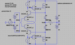
OK! 44Khz with nothing too evil happening. Phase & gain margins look good.
The big secret seems to have been De-Q'ing CDom with a series resistor!
The compensation itself was making the gain peak before it rolled.
I noticed you had snuck 10K into my signal source. Which was helpful in
rounding one of the other nuisance peaks quite a bit. But unfortunately
not the only gain peak causing trouble. I moved some of that out where
it can be more easily seen in the drawing.
15 ohms in an emitter tapped down the last one, such that the gain rolls
only downhill after the first pole. And the phase swings aren't so wild.
And little wiggle after the crest of each 22V @ 44KHz sine just vanishes.
You can see I now got -18db before the phase shift hits 120deg.
At higher frequencies than 44K at full swing, it can still distort pretty bad.
But I don't think it will ring or oscillate anymore. It should finally be stable?
And bootstraps are now back in place of the simulated CCS.
Attachments
Last edited:
I'll have to remember the de-Q thing.
Distortion has increased, but everything seems normal. Maybe we could replace R16 and R7 with lossy beads?
It operates very well from high source impedances.
You might want to add a .four analysis for the input point as well, so you can keep track of input impedance linearity; Q7 begins to saturate at 22V output.
- keantoken
Yeah yeah... 22V was about as far as I could here with 24V rails.
I'd like to keep all transistors out of both cutoff and saturation,
but thats really hard to do when your signal level is fully clipped.
No simple way the input cascodes could be bootstrapped for an
extra volt of headroom and still take necessary error measurement
from the collector.
Distortion now only .000012% at 1KHz 1VPP, how has this "increased?"
I recall it being somewhere in the .000083% zone before compensation.
The 2nd harmonic came up, but high order trash went down even more...
74LS logic puts a Schottky from base to collector, puts an absolute
limit how deep into saturation the transistor can go. I havn't given
proper thought weather or not that trick is of any use here? Won't
stop clipping, but might help recovery afterwards...
Last edited:
Distortion now only .000012% at 1KHz 1VPP, how has this "increased?"
I recall it being somewhere in the .000083% zone before compensation.
The 2nd harmonic came up, but high order trash went down even more...
It is a good thing.
At such low levels, 2nd harmonic is impossible to detect by the ear.
Just a small update. I've modified V6a with 2sa1837/2sc4793 as drivers. I ended up putting a 56pf mica cap between base and collector on these to prevent oscillation and they now run in the circuit. The simulation says that they should handle tougher loads. New sound card Juli@ measure .0023%THd on the V6a at about 1watt. V6a also runs all the way up to clipping with very small 2nd and 3rd order harmonics.
I was re-reading the thread looking for prefered Allison tranistors and came across keantoken's note about the That transistors being prefered for the allison pair. Do you still think this? I've been running KSA1381/KSC3503's.
Ken L
I was re-reading the thread looking for prefered Allison tranistors and came across keantoken's note about the That transistors being prefered for the allison pair. Do you still think this? I've been running KSA1381/KSC3503's.
Ken L
The THAT pairs are way too expensive and wouldn't provide any practical benefit here over the japanese ones. I suggested THAT arrays because of the tight matching which minimizes offset. In the V6, offset doesn't matter because that's taken care of by the LME49811.
The Allison relies on Gm of the transistors for gain. Since Gm is constant for BJT's, using different transistors won't really affect the audio performance, unless of course the transistors are slow or inferior and so cause oscillation.
Looking back I'm not so sure about that comment. It is certainly true for certain Allison variations which might be used as modular buffers for the bench, but when the Allison transistors are driving nonlinear driver Ib's, it may be a hassle and might ultimately be no more effective than using normal transistors.
- keantoken
Hello everyone, I'm gonna post this here to get it off my mind.
This was inspired when I read about the Bernie Olliver "Null point" in one of the Krill threads. This same idea should apply to any two diodes working in this way.
So here it is. I coughed up one of my goofy schematics into the simulator for the sole purpose of finding the null point (you can use any version of the Allison provided you can alter the bias voltage). For the MBR475 models with LTSpice, the null point is at about 1.37A. Tweak bias voltage of the Allison until you get there, and if you want to go further you'll have to tweak using the .four THD analysis.
So, it is still possible to have very low distortion levels with the Allison in class AB. The Allison AB begins to rival the class A Allison when you take into account that it is more powerful on power peaks (the class A version has output current limited to 2x the bias current). Now, I'm curious if it rivals the EF at null point.
- keantoken
Hello everyone, I'm gonna post this here to get it off my mind.
This was inspired when I read about the Bernie Olliver "Null point" in one of the Krill threads. This same idea should apply to any two diodes working in this way.
So here it is. I coughed up one of my goofy schematics into the simulator for the sole purpose of finding the null point (you can use any version of the Allison provided you can alter the bias voltage). For the MBR475 models with LTSpice, the null point is at about 1.37A. Tweak bias voltage of the Allison until you get there, and if you want to go further you'll have to tweak using the .four THD analysis.
So, it is still possible to have very low distortion levels with the Allison in class AB. The Allison AB begins to rival the class A Allison when you take into account that it is more powerful on power peaks (the class A version has output current limited to 2x the bias current). Now, I'm curious if it rivals the EF at null point.
- keantoken
keantoken,
Can you point me to the krill thread?
How about posting some results? How is this different/better than the adjustable Allison A/B?
Ken L
For the MBR475 models with LTSpice, the null point is at about 1.37A.
How do you come to this conclusion? For me, Schottky crossing distortion
forever goes down as bias goes up with no special sweet spot. An exact
bias shouldn't even matter where square laws rule, but even Schottkys
aren't perfect. What makes 1.37A some sort of magic number for "Null"?
Yet we aren't talking bout a whole lot of crossing distortion, even if biased
significantly closer to class B. Even approximated square law curve is good
that way, and thats the main reason to prefer them over log law bipolars.
Schottkys can approximate the right curve better than anything else but
MOSFETs or beam power tubes, and do so with minimal voltage drop and
minimum heat dissipation where actual curving decisions will be made!!!
I think it does make a difference the diodes are Schottky, and not just any
diode would do. Diodes must also be able to turn on and off without glitch.
Because doing so serves to keep back EMF from loudspeaker and bootstraps
from turning the power devices completely off. A bleed resistor across the
voltage gap (but not connected to the load) can then provide a minimum
do-nothing current to the power devices at all times.
Power devices that never turn off, implies conditions that make it fairly easy
to insure the entire drive train should never have to turn off.
Right now: I'm favoring about 300mA Schottky crossing, plus another 100mA
of do-nothing current, with acceptably low distortion.
Last edited:
It's not the circuit I posted but the concept!
There is some point observed by a guy named Bernie Olliver, where the transfer curves of two BJT's cancel out and distortion drops. Here is the post I mentioned:
http://www.diyaudio.com/forums/solid-state/151295-krill-next-generation-9.html#post2085739
This will work with any Allison circuit, and with the bias current I specified if you use LTSpice's default MBR745 model.
It may appear that distortion steadily decreases with the transition into class A, but this is not true. Keep going up in small increments from, say, 100mA for a bipolar EF stage, and looking at the THD number until it starts to increase again. Then turn it down in smaller increments until you find the null point.
- keantoken
Last edited:
- Home
- Amplifiers
- Solid State
- Simulation Analysis of several unique Allison-based output stages.