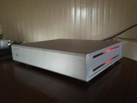
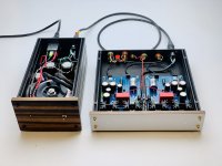
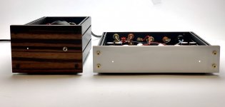
Adjusted for 3.6V both channels, finished the case and hooked it up.
It is dead silent, even with the transformers in the case. no hum at all.
it sounds promising from the start. i will let it play for a while before commenting on the sound.
Thank you Salas and Theabag for this awesome piece of kit, well done.
regards,
John
It is dead silent, even with the transformers in the case. no hum at all.
it sounds promising from the start. i will let it play for a while before commenting on the sound.
Thank you Salas and Theabag for this awesome piece of kit, well done.
regards,
John
Attachments
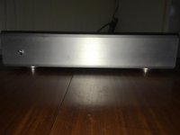
Great chassis work. The side openings with glimpse to the circuit's Leds ambient effect look particularly nice. Congratulations 
well, mechanical work (milling, lathework, etc) is easy for me.
Electronics however, not so much.
But with great help from the diy forum members in came out great.
regards,
John
Electronics however, not so much.
But with great help from the diy forum members in came out great.
regards,
John
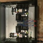
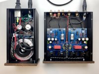
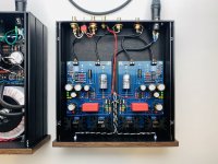
Finally had some time over the holidays to test and box my FSP.
It took a bit of trial and error to get the PSU input voltage in the right range, but now sitting at about 45.2 VDC off the cap multipliers (these reduced input ripple from about 38mV to about <1mV). Led’s on the cap mx are glowing a bit which is worrying - everything measures okay, but they may be a bit stressed because they are at their operating limit (~45V).
Started up without an issue, and regulated voltage is 33.6V right and 33.8 V left, with setup for mc. Tricky setting bias because as soon as I remove the lid to adjust, the voltage starts to drift - perhaps because of the temp change on the jfets? Best that I can get is 3.6V +/- 10 mV. Is that adequate tolerance or should one try again?
Regardless, here is a picture during biasing - I’ll update when I have done some listening.
Many thanks to Salas for this design, and to Teabag for the gb and sourcing some difficult to find parts.
Attachments
You are welcome and congratulations for your build so far.
There's absolutely no problem with different rail settings tolerance between channels or thermal drift of input stage DC voltage centering (T.P.) especially manifested in MC mode. Such is the nature of things with 2SK369 when run at high Id mA due to small value degeneration resistors in this mode. But that's best for noise performance. In reality there is much leeway allowed left and right of the 3.6V T.P. center for several hundreds mV level signal to develop between end stops even if bias point drift is going to augment a lot with time or season.
There's absolutely no problem with different rail settings tolerance between channels or thermal drift of input stage DC voltage centering (T.P.) especially manifested in MC mode. Such is the nature of things with 2SK369 when run at high Id mA due to small value degeneration resistors in this mode. But that's best for noise performance. In reality there is much leeway allowed left and right of the 3.6V T.P. center for several hundreds mV level signal to develop between end stops even if bias point drift is going to augment a lot with time or season.
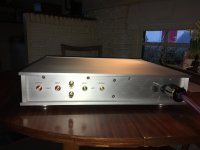
Why you installed two GND lugs?
my turntable has two ground wires with banana plugs, when needed i can just plug it in easily instead of trying to get two wires through a small hole on the back.
and also because i can 😀
regards,
John
It depends. It has more yfs and capacitance. Could be inadequate in certain positions. In any case must recalculate values around it. Not in this circuit as it is.
Greetings,
I have just completed my build of the phono preamp using the minikit provided by TeaBag. I'm having a problem setting the bias. The maximum voltage I can get between the RAIL+ and GND test points is about 29 V. I'm using a 36VAC transformer and providing about 55 VDC from the raw power supply.
I will appreciate any guidance.
Thank you sir, that solved the problem. I replaced R3x with 12k and now everything is fine. I assume I don't need to change R6x (it's 22 ohm). Now I just need to get this cased so I can give it a listen and see how it compares to Pearl II and Pete's LR Phono preamp (my 2 favorites).
Also put 20R 2W RD/Link resistors in the Raw DC board to drop its VDC output. You don't need 55V it will much increase the heat dissipation for Q1x Mosfet in the shunt regulator for no other good return.
Hey guys, made this incredible phono pre over the weekend at “Camp 6L6”. Been in the making for a while now... and I definitely needed help since it’s beyond my current skills (which we all know Jim has in spades. 🙂 ) Learned a TON, and it sounds incredible.
Little drama with some hum.. wasn’t a lot.... but 2 perfectionists sorted it out. VERY quiet now and I can’t imagine a better sounding phono pre.
HUGE thanks to Salas and Tea for the insightful design and parts connect.
Seriously amazing build both in visual design and application.
Little drama with some hum.. wasn’t a lot.... but 2 perfectionists sorted it out. VERY quiet now and I can’t imagine a better sounding phono pre.
HUGE thanks to Salas and Tea for the insightful design and parts connect.
Seriously amazing build both in visual design and application.
Attachments
Last edited by a moderator:
- Home
- Source & Line
- Analogue Source
- Simplistic NJFET RIAA