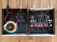
Do you mean something like that (since braid must be GNDed at some point, otherwise it will not stop RF)?
That is what I have done apart that the cable run go from cartridge to 5 pin
Plug (Even the metal body on plug is totally independent from cable returns)
there are no solder joint's and the silver cable is the same material as the cable in the coils of the Elitte
Increasing in value yes. I had decreasing the HF response in mind.
loading the DL-110 with 1k2 gave better result than adding 300pF in the RIAA in my system. Guess mainly due to the cart.
I will try another Rload value from 1 to 8k (as seen here)
By the way, is it relevant to burn the capacitor with circuit like sample wav (pink, white noise) from a cd to a cap tight to ground with some R in parallel.
Just to gain time for the cartridge lifetime ?
I am not sure if very low loss plastic caps ever "burn". Electrolytics surely shape up after storage though. But you can use an L pad 100 times attenuator made from two resistors (1k series 10R to ground) and feed the phono any kind line level signal through it for any purpose.
Plastic film caps have a de-rating when frequency becomes high.
I think this is due to the heating of AC current through the cap ESR.
I think this is due to the heating of AC current through the cap ESR.
with line out at 2v, won't it give about 20mV ? If so, is it not too high if feeding directly the pre ?
2V is max RMS red book. I.e. 0dbFS. Measure your line output RMS first with true RMS DMM (selector on AC) for the program material and volume level you intend to use. Its usually much lower than 2V RMS. Then its easy to decide the L pad ratio for say 1mV RMS downscaling.
One channel is as expected, TP1 - TP2 measured 4.4 and a turn on VR2x took it to 3.8 and another small tweak after a couple of minutes took it to 3.6v.
The other channel though the led's in d1 to d4 have gone out, any ideas why? Both channels were adjusted to 35v using VR2x and left to warm up.
The other channel though the led's in d1 to d4 have gone out, any ideas why? Both channels were adjusted to 35v using VR2x and left to warm up.
In fact on returning the working channel is back to 3.8 at tp1-tp2
The guide says use B+ to adjust?
The guide says use B+ to adjust?
The d1-d4 that don't light up maybe got one or more of those leds reversely oriented?
The tp1-tp2 can play with warm up. Adjust it after half an hour from cold start.
Vr2 adjusts b+ and that changes the tp reading
The tp1-tp2 can play with warm up. Adjust it after half an hour from cold start.
Vr2 adjusts b+ and that changes the tp reading
They did at the start but then went out when left to warm up after adjusting rail+ and ground reading to 35v.
tp1-tp2 reads 20v on that channel.
tp1-tp2 reads 20v on that channel.
So some Led there was weak and went out. Maybe the soldering tortured it. 3mm Leds are kinda sensitive. Go there with the DMM in diode mode and measure one by one. No need to remove them for finding which one conducts and which one doesn't. Find the culprit(s) and replace them. If they are good maybe Q7 is out. Its their current feeder.
Many thanks Salas, up and running and already sounding pretty damn good after 45 minutes.
Just ordered a new DMM to measure capacitors and leds which will let me tweak it in needed...
Sent from my LG-V500 using Tapatalk
Just ordered a new DMM to measure capacitors and leds which will let me tweak it in needed...
Sent from my LG-V500 using Tapatalk
- Home
- Source & Line
- Analogue Source
- Simplistic NJFET RIAA

