I think you should use each coax's shield as minus return side for the respective cart channels that their cores will carry separately and a separate simple wire for the fork to the arm's chassis.
I see. I'll test such structure tomorrow . I'll update ASAP. Thank you a lot for your tremendous support.
Sent from my iPhone using Tapatalk
Sent from my iPhone using Tapatalk
If you use a twisted pair and screen/shield on each channel, then the twisted pair are the signal wires.I see. At that case I'll might try Mogami w2549 - two twisted wires with braid. I'll use two of those: one for L and and one for R. The question is where to connect braids together to avoid loop: I must connect arm GND to braid at the arm side, then I need to connect braids again at RCA side and solder wire with Fork.
The screen/shield does NOT connect to the audio, anywhere.
The screen for each channel goes to the chassis/enclosure at the point of entry.
Connecting the two screens to the enclosure does NOT create a loop in the audio circuits.
If you use a coaxial cable where the core is signal hot and the screen is signal cold, then these two wires go to the audio connections at the RIAA input.
These two audio connections are not connected to chassis/enclosure.
Connecting the two channels with one pair of coaxials should not create a loop in the audio circuitry. Because at the cartridge the two signal colds are NOT CONNECTED.
It is AFTER the RIAA where channels can share a common (unbalanced) audio ground that loops will be created.
Salas,
does the INPUT to the RIAA have a shared signal return/cold between the two channels?
Last edited:
Alexk,
does your arm output cable move?
Could be due to arm rotating, or due to a spring suspended sub-chassis.
If the arm output cable moves, then you must build in adequate compliance in the cable connection so that the movement is allowed.
This usually demands a very small pair of very soft coaxial cables, that can be located as "soft" springs, that do not impede arm movement.
A pair of twisted wires in a screen with insulation will be quite stiff and may never be adequately compliant for a moving arm.
Salas,
does the INPUT to the RIAA have a shared signal return/cold between the two channels?
No, they are double mono separate boards.
The question is where to connect braids together to avoid loop:
....................
Salas,
does the INPUT to the RIAA have a shared signal return/cold between the two channels?
Then Alexk does not have any loops at the input to the RIAA.No, they are double mono separate boards.
Are the Teflon and the Mundorf same value? And what is that value?
Same value, 0.1uf, scr teflon , fep series (scr is known as solen if i'm not wrong)
Those are very clear capacitors. You maybe need to revise your C2Y down a bit from what it was chosen with the film & oil cap so it will balance out while retaining the clarity.
Clear and harsh in the high. But as Teflon is said to be smooth after break in, i will give it a try.
I also tried 1k2 Zfoil to load the DL110 (proof of concept to see if it's worth buying 47k). The high was recessed, but overall details was clearly better. I will try again with those teflon one.
I also tried 1k2 Zfoil to load the DL110 (proof of concept to see if it's worth buying 47k). The high was recessed, but overall details was clearly better. I will try again with those teflon one.
Then Alexk does not have any loops at the input to the RIAA.
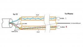
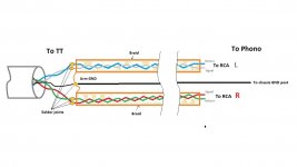
I made that picture in order to finalize how it is looks . The only issue is the diameter of these two cables combine. I have 6mm hole in rivet to insert that. Hope you did see my TT pictures uploaded 2 days ago.
Arm motion is not limited since very tightly silk coated wires with cart clips are running through the arm. Phono cable is soldered to these wires at the vertical cylinder uses as ARM holder and for VTA adjustment piece. Please see my 2 days old pictures for TT Arm construction.
Attachments
Last edited:
I personally would not gamble to mix the chassis ground with any signal shields. Especially if I had the pops incidents. I would go for single core coax per channel and a chassis wire. There are thin flexible RF cables when the collar diameter is restrictive. But each one tries own approach first and if its pop free so far so good.
It is not mixing or I was mistaken during picture creation...
TT has independent Black wire that connected to the carbon-fiber tube and will solder it to braid at TT side. On other cable side, braid also will ne connected and I'll solder other Black wire with Fork.
Signal GNDs are Blue and Green.
TT has independent Black wire that connected to the carbon-fiber tube and will solder it to braid at TT side. On other cable side, braid also will ne connected and I'll solder other Black wire with Fork.
Signal GNDs are Blue and Green.
Just test it. Low level signal connections in various TTs are weird to predict for best noise immunity. Its DIY so you can change it again.
Sounds good. 🙂. Can you please help me to find dissent quality cables with such balance design?
All what I see is thick for my TT rivet hole.
All what I see is thick for my TT rivet hole.
- Home
- Source & Line
- Analogue Source
- Simplistic NJFET RIAA