Thanks to Tea B I finally got a new mosfet in there,everything light up Now🙂.now need some adjusting.Now my power supply voltage drop to 37 voltage at DC end when hook up and both fire up?😱 it that normal?
lapsan
You mean raw DC at board input level? That's too low. If you got Vdrop on the 15Ω resistors suggesting about 100mA through each, then the boards are OK but the raw PSU has a mistake or some wrong spec.
Thank you,i got it back to 48volt at the input,on one rail is 34.6 volt and on another rail is 30.6 volt so far,i'm trying to bring that up to match the other side.You mean raw DC at board input level? That's too low. If you got Vdrop on the 15Ω resistors suggesting about 100mA through each, then the boards are OK but the raw PSU has a mistake or some wrong spec.
Turbon,
I will. But don't you want me to get it working first? I don't want to be responsible for a fire in your house. I don't have a transformer yet...But should be soon.
Sure - good idea 🙂
Regards
Regarding my 20x Hong Kong eBay purchased 2SK117GR:
I am getting between 4mA and 6mA IDSS, so all within GR spec.
Most obvious quality is almost zero thermal drift, and immediate reading does not change, as compared to almost opposite experience testing K170 fets. Is this a sign that they are genuine?
I am getting between 4mA and 6mA IDSS, so all within GR spec.
Most obvious quality is almost zero thermal drift, and immediate reading does not change, as compared to almost opposite experience testing K170 fets. Is this a sign that they are genuine?
Also regarding 2SK117, I have selected 4.92 pair for main circuit, but have nothing between 3mA and 4mA for the x6 I need on the regulator circuit. Can I use 4.5 - 5mA. What issues might this cause? Thank you.
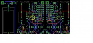
stupid question,where is TP2?,I think i'm blind .Thanks
lapsan
Here it is....in Yellow.
Attachments
Hi Hikari1.
Would you mind upload a drawing of how you place the components on your protoboard?
It would be very appreciated🙂
Regards
Turbon,
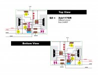
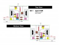
Here is what I am thinking for layout. IT IS UNTESTED, there may be mistakes. It is sized for 7x9cm protoboard. The gray area is heatsink. Feel free to comment or give suggestions.
Attachments
Turbon,
Here is what I am thinking for layout. IT IS UNTESTED, there may be mistakes. It is sized for 7x9cm protoboard. The gray area is heatsink. Feel free to comment or give suggestions.
Hi Hikari1.
Looked it thru and I believe it will work. The only mistake is that the cap marked C1 100uf close to Q2 is actually C2.
Regards
View attachment 442865
I think Q3 was upside down as well. Here is a revised layout.
Hi Hikari1.
Looked it thru and I believe it will work. The only mistake is that the cap marked C1 100uf close to Q2 is actually C2.
Regards
I think Q3 was upside down as well. Here is a revised layout.
Attachments
Last edited:
BF 245 or 2N5457
Can you name a reliable vendor of 12 transistors BF 245 or 2n5457, please ?
I have difficulties finding such vendor.
Thank you, very much.
Can you name a reliable vendor of 12 transistors BF 245 or 2n5457, please ?
I have difficulties finding such vendor.
Thank you, very much.
Building the pcb version...
Well, I decided to build a 40db gain version using the pcb's instead as I have a kit. Saved it for another 63db build but as I have oldie goodie mm carts I wan't to give them the respect of something documented good. It feels as a more secure path with support from the designer.
Regards
Well, I decided to build a 40db gain version using the pcb's instead as I have a kit. Saved it for another 63db build but as I have oldie goodie mm carts I wan't to give them the respect of something documented good. It feels as a more secure path with support from the designer.
Regards
Well, I decided to build a 40db gain version using the pcb's instead as I have a kit. Saved it for another 63db build but as I have oldie goodie mm carts I wan't to give them the respect of something documented good. It feels as a more secure path with support from the designer.
Regards
Actually, mine is a 40db version too. PCB is a good idea, when I started mine the group buy was not going yet, and I wanted to use batteries initially because I didn't have a suitable transformer or case. But yes, the PCB should be good.
I am using a Ortofon 2M bronze on a Rega P5 with the Nfet phono (using batteries) now. It is amazing. I hope the shunt is better than batteries but it will be worth it just to not have to monitor the voltage and replace batteries all the time.
Hikari1, I'm sure that the shunt will outshine the batteries. I'm equally sure that the whole will astonishe you in it's brilliance. I choose the easy path as I have most of the parts needed.
Regards
- Home
- Source & Line
- Analogue Source
- Simplistic NJFET RIAA