Are you sure.Reverse the battery's polarity. ...........
The battery + is connected to red.
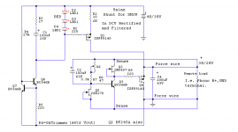
That red passes into the 10r. the 10r feeds the Drain pin.
That, to me, looks right.
Oops, there is a view of a black going between the terminals. Is Black feeding right hand terminal and then the resistor and the next red wire?
The hand written labels on the paper have been reversed
It's the wires into the terminals that have been swapped.
Last edited:
Andrew, I think Salas is right.
That + is not passing into the resistor and feeding the drain in the picture. Looking behind the connector block, we can clearly see the black - cable passing over to the resistor side of the connector block. The + and - markings are written as it is wired, with reversed polarity from how it should be.
That + is not passing into the resistor and feeding the drain in the picture. Looking behind the connector block, we can clearly see the black - cable passing over to the resistor side of the connector block. The + and - markings are written as it is wired, with reversed polarity from how it should be.
It's all good guys, thank you. The pic is a little confusing I suppose. I swapped polarity and all works well.
Use red for +ve supply, always and then you "inspect" instantly.
BTW,
I clip a red croc clip to the two leads S+G first.
Then clip a black croc to the remaining lead.
This achieves two outcomes.
1.) S& G are shorted BEFORE applying power.
2.) Vds, Vgs and Vdg cannot be taken beyond limits because S&G are already shorted.
Inserting a 3pin device into a live socket has the risk that two pins can be connected before the third pin makes contact. That can destroy some devices.
Last edited:
Hi guys, my build has slowed down as I'm waiting on more parts.😡 I still need to order C2x and I can't get Wima mkp or mcap evo, would Jantzen mkp cross cap be suitable?
Hi guys, my build has slowed down as I'm waiting on more parts.😡 I still need to order C2x and I can't get Wima mkp or mcap evo, would Jantzen mkp cross cap be suitable?
Of course it would be fine. They're not bad caps at all. My speakers are full of them, and sound dreamy.
All,
About to put together the V1.1 shunt to feed my Salas phono...anybody have a perfboard layout or pcb design for this version of the shunt? I've sketched out about 10 different versions on paper but it's giving me a headache. I managed to get the phono put together point to point but this one is hurting my brain.
Thanks.
Attachments
Some circuits really do benefit from a beautifully put together PCB. Fortunately for us, there is one for the folded simplistic circuit.
Why don't you us that one for your layout inspiration!
Why don't you us that one for your layout inspiration!
Last edited:
See this start of this thread for the layout:
http://www.diyaudio.com/forums/group-buys/241736-gb-salas-folded-simplistic-phono-pcb.html
http://www.diyaudio.com/forums/group-buys/241736-gb-salas-folded-simplistic-phono-pcb.html
I just finish assemble the board ,no power on the rail or TP1?i don't know what when went wrong Thanks
lap
lap
First make sure you got incoming DC right for value and polarity to the boards. Next debug the regulators area. Check MOSFET types are right etc.
All,
About to put together the V1.1 shunt to feed my Salas phono...anybody have a perfboard layout or pcb design for this version of the shunt? I've sketched out about 10 different versions on paper but it's giving me a headache. I managed to get the phono put together point to point but this one is hurting my brain.
Thanks.
Some circuits really do benefit from a beautifully put together PCB. Fortunately for us, there is one for the folded simplistic circuit.
Why don't you us that one for your layout inspiration!
Or get a bib 1.1 board from Tea if he has got any left from last GB. Carries two positives and you can break off the negative area, its all V grooved in three sections.
Dc voltage is 47 voltage,i will reduce it further with a bigger resister at later when i place an order tommorow.the Mosfet is IRF9610PBF Q1x 2-IRF9530PBF Q6x 2,Tea hook me up great packet 😀First make sure you got incoming DC right for value and polarity to the boards. Next debug the regulators area. Check MOSFET types are right etc.
lap
lap
You don't have to reduce from 47 raw DC, its already in spec. Look for correct polarity to the DC in connector and/or parts stuffing mistakes in the regulators. Like having used a BJT for a JFET or the other way around, a PNP instead of an NPN, some wrong resistor...
i unsoldering the big cap and look at Jfet.everything look exactly the same thing on other side.the other side work fine.all the jfet test fine when Tea sent the packet.Thanks again
lap
lap
- Home
- Source & Line
- Analogue Source
- Simplistic NJFET RIAA