I don't have 2sk369
I did do high range of bl grade 2sk170 and many throughout the range of c grade lsk170, some exceeding 20mA Idss with their very high gm.
Maybe because you keep G+S in minimal distance just tied with a crock.
What do you know. I had a NPN/PNP-module on one of my meters.😱
First row is Mikes, next is some I had. Ok Hfe?
HFE very good.
I just noticed this:
That was with gate and source connected together. Where did the other 0.5V go? What was between the gate and source that would have dropped half a volt at a few mA of current?
I would say so yes. Just like an LM 317 has its internal reference voltage I guess. I'm clueless about sand-stuff.
My point was that the gate and source were connected together and should be at the same potential. Half a volt is a big difference there.
My point was that the gate and source were connected together and should be at the same potential. Half a volt is a big difference there.
Must have been Drain to Source-Gate. I was tired. I just left some measures for clues. This showed up good cause Salas pointed out that I used double voltage then in real circuit.
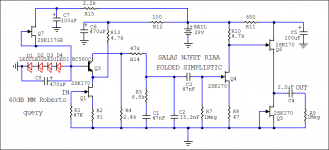
Use the smallest IDSS 170BL you got in place of the K117GR or better use BF245A if you got any. See to have about 10V between R15 and D4 (across Q7) and adjust the R15 value for that. (Or R12, D1, Q5, in your #12842).
P.S. Match your FETS to a fair degree, and use your best matches in the second stage.
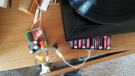
I've got one channel up and running! It works, it makes sound although it's hard to judge with only one channel.
But I've only got about 2.6V across R15 and D4. I am using an 8ma 2sk170 for Q7. Can you suggest a value for R15 to get me in the 10V range across r15 and D4 or is it to leave it as-is? The gain was maybe a little lower than I expected but again, it's hard to tell with only one channel.
Attachments
Anyway you have provoked an interesting discussion and analysis. 🙂
For me its always interesting in trying to understand what I do and why. Learning from masters by building their builds and ask alot of stupid questions is one way😀
I've got one channel up and running! It works, it makes sound although it's hard to judge with only one channel.
But I've only got about 2.6V across R15 and D4. I am using an 8ma 2sk170 for Q7. Can you suggest a value for R15 to get me in the 10V range across r15 and D4 or is it to leave it as-is? The gain was maybe a little lower than I expected but again, it's hard to tell with only one channel.
Q7 still works as CCS with only 2.6V VDS too because its a low pinch off FET. You can use 1.2K R15 at a point, but its not a pressing issue.
More of a priority is to check voltage across R4. How much is it? Also, what Rail+ those batteries provide?
@Stajo
There should be just a loss expressing RDS * ID. If no loss, the FET would have no dissipation.
There should be just a loss expressing RDS * ID. If no loss, the FET would have no dissipation.
Ok. I learn something new everyday 🙂 How to Calculate the Drain-Source Resistance, RDS, of a JFET Transistor?
possibly, but the MAIN reason for clipping the S+G together BEFORE applying power is to ENSURE no damage to the device.Maybe because you keep G+S in minimal distance just tied with a crock.
The clipped pair are the Source leads and ALWAYs go to the respective Nchannnel or Pchannel supply voltage.
The clipped pair also means one can never misapply excessive gate to source voltage, if a clip, or socket, or other connection makes intermittent contact.
2.6V across R15 indicates ONLY 1.18mA flowing through the CCS jFET (2.6V/2k2= 0.0011818A)I've got one channel up and running! It works, it makes sound although it's hard to judge with only one channel.
But I've only got about 2.6V across R15 and D4. I am using an 8ma 2sk170 for Q7. Can you suggest a value for R15 to get me in the 10V range across r15 and D4 or is it to leave it as-is? The gain was maybe a little lower than I expected but again, it's hard to tell with only one channel.
There is something wrong.
What is the voltage across the LED string? d1? d2? d3? d4? (d1+d2+d3+d4)?
That's a good one to keep safe for re-use later.Ok. I learn something new everyday 🙂 How to Calculate the Drain-Source Resistance, RDS, of a JFET Transistor?
Now where can I put it so that I know where to look for it?
if there is 2.6Vds on the jFET I'd expect the Id to be very approximately half Idss.
That can be checked by measuring the Vr15 and calculating the current passing to the CCS.
That can be checked by measuring the Vr15 and calculating the current passing to the CCS.
Not so much loss, even at 0.6V VDS a K170 loses 20% IDSS only. About 7% IDSS loss @ 2.6VDS vs 10VDS.
if there is 2.6Vds on the jFET I'd expect the Id to be very approximately half Idss.
That can be checked by measuring the Vr15 and calculating the current passing to the CCS.
That can be checked and is worth checking by measuring Vr15.Not so much loss, even at 0.6V VDS a K170 loses 20% IDSS only. About 7% IDSS loss @ 2.6VDS vs 10VDS.
And written down on his printed schematic for future reference. Along with all the other relevant node voltages.
Q7 still works as CCS with only 2.6V VDS too because its a low pinch off FET. You can use 1.2K R15 at a point, but its not a pressing issue.
More of a priority is to check voltage across R4. How much is it? Also, what Rail+ those batteries provide?
Batteries are about 27.5V unloaded. They are a little used so I expect about 30V loaded with fresh batteries.
I've got 3.6V across R4. I have a trimmer I can adjust if needed.
Thanks Salas.
- Home
- Source & Line
- Analogue Source
- Simplistic NJFET RIAA