Yep, increase R3X. Tp1-tp2 follows that situation. You basically read the LEDS to ground or about the same for now. Its suspicious though in case Q3X is not confirmed as low IDSS (less than 3.5mA) so to be the only reason to have low Rail+ now.
I found in practive ones above 4.5ma Q3x where hard to get into zone, and ones above 5.5ma hard to down into that range. It may be best to swap Q3x to see which works best, making sure you measured them all as specified in the build guide.
I use 500mm long croc clip leads for rough batching of jFET Idss.
Never had a problem with instability.
Did you try that with K369s or alike models? Me I had encountered instability with those especially if on breadboard and the G to S link is patch wire and not a short pin link. Also with different DMMs and leads if in series mode. It will not come up with a FLUKE 87V but it will with a UNI-T.
Any range that I should prefer on Q7 before lining up the LEDs?
Use 4.9 + 4.91 Q3X with the 6K2 R3X.
Ok thanks. To be clear, i have most ranges between 2,8-6mA if i should prefer any other values.
Use 4.9 + 4.91 Q3X with the 6K2 R3X.
So, should I exchange my 9K1 to 6K2? I think I choosed something like 3,5 mA for Q3x but I can easily desolder it as well as R3x if higher values are prefered.
Its just another valid combination. Should give you 29-35V Rail+ range as it is. The other combo will give you 27.65-36V Rail+. The now combo will be more analytic in its range.
Ok thanks. I'll let 3,5ish Q3x sit as well as 9K1 R3x then. Q7 4,6 then? Any value to Q2x to prefer with R6x 22R? Q5x I have something in that 3,5ish also.
Q7 4.6ish is perfect. Q2X will see across raw-triplet = 43VDC roughly in your case. 22R will degenerate it to about 3mA, so about 130mW will handle safely.
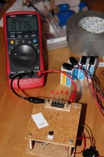
Cool. I did Q7+quartet first. Since current is low I can not just add singlehandingly measured LEDs to eachother but has to go up slightly in values.
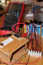
First 4,62 mA Idss I tried with LEDs that individually measured 1,965, 1,971, 1,973 and 1,972. That quadruple that should end up on 7,88 at larger current here ended up on 7,72. So I exchanged the 1,965 with a 2,000 and a stable total ended up on 7,75 volts.
Same procedure with next 4,60 mA. There I ended up with 1,974, 1,970, 1,969 and 2,003 LEDs stabilizing at 7,75 V.
Measured over 18 V.
Now, the question is what will happen when Q3 starts to take some current. Maybe I should solder one diode with long pins to make it easily exchangable.
Attachments
Last edited:
Nothing will happen. Q3 will take IC/HFE through its Base. Mike's Fairchilds hit in the 650 HFE. Now divide 1.8mA IC by 650.
I don't have 2sk369Did you try that with K369s or alike models? Me I had encountered instability with those especially if on breadboard and the G to S link is patch wire and not a short pin link. Also with different DMMs and leads if in series mode. It will not come up with a FLUKE 87V but it will with a UNI-T.
I did do high range of bl grade 2sk170 and many throughout the range of c grade lsk170, some exceeding 20mA Idss with their very high gm.
Last edited:
Testing out D2,3,4x plus a 3,8 mA K117 with a 22R on its Source was not doable with high value reds, I ended up with one high value red (2,1V) and two greens to reach 5,80 V over the leds. 48 V over the lot.
Attachments
Last edited:
About Q4x, BC560C. It says 7% hfe match. Do I need like an Atlas component analyzer for that or is there any other way?
I just noticed this:
That was with gate and source connected together. Where did the other 0.5V go? What was between the gate and source that would have dropped half a volt at a few mA of current?
Drain-source measures some 38,5, drain-gate some 39,0.
That was with gate and source connected together. Where did the other 0.5V go? What was between the gate and source that would have dropped half a volt at a few mA of current?
- Home
- Source & Line
- Analogue Source
- Simplistic NJFET RIAA
