Here you go...🙂.
Very nice indeed. The government here doesn't let the boxes be visible so they are hidden in a cramped environment behind the CD's. So temperature was a problem. Well, I don't mind changing the elyths when the time comes. I still have a bit of tweaking to do but I leave it for my second build so I can enjoy the first while figuring out the parts 🙂
Regards
Turbon, can you explain this governmental restriction a bit more? I'd like to know what it's about.
Turbon, can you explain this governmental restriction a bit more? I'd like to know what it's about.
Hi Kean.
Marriage and taste are the keywords 😉
Regards
Kean, what you changed and Alex has 2V drop on CCS load now when before he and skouliki had troubles with suspicious excess drop over previous KM-Mult?
I have done nothing but add some shunt diodes that can handle the severe inrush at high voltages, while preventing the transistors from seeing too much Vce at inrush. You don't get a smooth startup voltage ramp, but this is necessary to protect the transistors from inrush with high input voltages. Honestly, I'm not sure how necessary it really is, but I go by the datasheet max specs.
As I recall those who have had problems have found the cause and fixed it. A few times it was because of a missing input cap. Even the Kmultiplier doesn't do well without an input cap - this is a restriction that applies to all active low-Zout series filters/regulators. I've made some oversights when I wrote the Kmultiplier page and provided the initial specifications, but as far as I can tell everyone's happy.
As I recall those who have had problems have found the cause and fixed it. A few times it was because of a missing input cap. Even the Kmultiplier doesn't do well without an input cap - this is a restriction that applies to all active low-Zout series filters/regulators. I've made some oversights when I wrote the Kmultiplier page and provided the initial specifications, but as far as I can tell everyone's happy.
Is flat & low Z source characteristic like the KM has beneficial when the load is an active CCS vs a two stage higher rejection overall but ascending under 100Hz Zo classic Cmult cascade or second order or Darlington etc.?this is a restriction that applies to all active low-Zout series filters/regulators.
hi Kean
So this new schematic is better suited for input voltages around 45 ~ 50v ?
RC, are you referring to Keans links or one-off earlier in the thread?
Regards
RC, are you referring to Keans links or one-off earlier in the thread?
Regards
I refer to post 12512 where I see a new Kmult http://www.diyaudio.com/forums/analogue-source/129126-simplistic-njfet-riaa-1252.html#post3893202
Look in the "other adaptations" section of my Kmultiplier page that I just updated. That version is safest for 45V and up. Those of you have have asked me for circuits in this range I have given safe schematics for, so no need to worry and there's no point in upgrading.
Look in the "other adaptations" section of my Kmultiplier page that I just updated. That version is safest for 45V and up. Those of you have have asked me for circuits in this range I have given safe schematics for, so no need to worry and there's no point in upgrading.
Yes, right. Thanks RC and Kean. Wrote that up for consideration for the next build 😀
Is flat & low Z source characteristic like the KM has beneficial when the load is an active CCS vs a two stage higher rejection overall but ascending under 100Hz Zo classic Cmult cascade or second order or Darlington etc.?
I don't have a reason to think that low Zout like the KM would benefit a CCS, but I've talked with several people who say it improves the sound. Based on my understanding of electronics theory I wouldn't focus on low Zout for powering a CCS, if I could do it simpler with the same PSRR. In this sense the main feature of a KM would be lower voltage drop than a 2-transistor cascaded C-multiplier. For this specific application the two options seem fairly close, but I haven't done an actual comparison along these lines.
not too beautiful, not too compact, not too professional.
but it sounds!
thanks Mr Salas!
but it sounds!
thanks Mr Salas!
An externally hosted image should be here but it was not working when we last tested it.
An externally hosted image should be here but it was not working when we last tested it.
An externally hosted image should be here but it was not working when we last tested it.
An externally hosted image should be here but it was not working when we last tested it.
An externally hosted image should be here but it was not working when we last tested it.
Last edited:
Bravo! Did you manage enough gain for your MM cartridges? Match between channels loudness is good? Only sounds, or you listened properly to records already and its fully OK?
at this time ........ only sounds.
the second channel suffers almost the same problems as the other problems that you have solved.
I hope to solve them also in this case.
I noticed that connecting both channels to the voltage, this is considerably lower.
The transformer is a 24 volt / 4 A.
is not in use your shunt regulator but this:
Simple Voltage Regulators Part 1: Noise
with the 27v diode.
I apologize but at this moment "the convent pass this".
 , the transformer is 21v / 3A.
I also noticed these issues:
- on the collector of Bc560c(Q3) channel that works badly, I measure 1.8 V, while on the channel working I measure 3.4v.
replaced the Bc560c(Q3) but nothing has changed.
- the same resistor(R13), same value, same lot, delivers a lower voltage: almost 1v less. for me this is unbelievable! 😱
- on the collector of Bc560c(Q3) channel that works badly, I measure 1.8 V, while on the channel working I measure 3.4v.
replaced the Bc560c(Q3) but nothing has changed.
- the same resistor(R13), same value, same lot, delivers a lower voltage: almost 1v less. for me this is unbelievable! 😱
Its you did not match IDSS probably? In the 1.8V channel make the 100 Ohm R12 smaller until it goes 3.4V there too. Best is 4V in both channels, your 27V creates less current than 28V rail spec on your personal single K170 MM version already.
is not in use your shunt regulator but this:
Simple Voltage Regulators Part 1: Noise
with the 27v diode.
I apologize but at this moment "the convent pass this".
Is this reg with small TO-92 transistors capable enough? Your version needs 20-22mA per channel. Maybe BD140 for Q2 if its a common reg between channels.
I don't have a reason to think that low Zout like the KM would benefit a CCS, but I've talked with several people who say it improves the sound. Based on my understanding of electronics theory I wouldn't focus on low Zout for powering a CCS, if I could do it simpler with the same PSRR. In this sense the main feature of a KM would be lower voltage drop than a 2-transistor cascaded C-multiplier. For this specific application the two options seem fairly close, but I haven't done an actual comparison along these lines.
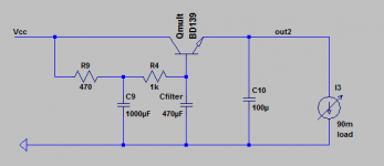
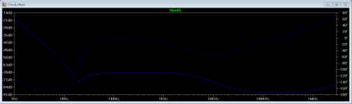
I have looked for parts in my boxes, I put on Spice based on those parts, maybe I will give it a go out of curiosity. 1.4V drop. What you think?
Attachments
- Home
- Source & Line
- Analogue Source
- Simplistic NJFET RIAA