After some work.... (started with a bunch of small caps 10pF 33pF 40pF 47pF 56pF) for C2y, I finally got the rig singing... and I mean Really singing... I must congratulate Salas and Teabag for the splendid work on the design, component values choice, clear pdf and wonderful pcb.
As usual I started with C1, being very carefull to get a close match between channels.... I measured 20 pairs and settled for 47.4nF obbligato caps.
Please bear my simple math:
2187 / 0.0474 = 46139 So I needed to get R14 + R4 // R7 to be near 46139
I searched my stock and found:
R14 = 47200 // 2M02 = 46122
R4 = 2200 sharp so:
R4 + R14 = 46122 + 2200 = 48322
For R7 I got 0.991M ohms
So total resistance is 48322 // 0.991M = 46076ohms (quite near 46139) I rest my case 🙂
Now 750 / 46076 = 0.016277 ( 16.277nF) and that is what I needed for C2
Based on (several) previous folded builds, I estimated second stage Miller to be near 1.03nF
So I needed 16.277 - 1.03 = 15.24nF for C2
Found in my stock a really nicely matched pair of copper foils measuring 15.2nF and so I estimated the need for 40pF C2y.
After first listening sessions I found this PCB folded to sound really good but not magical (I was using only the stock 15.2nF for C2) and so started to experiment.... as you might have read in the beginning, I used caps ranging from 10pF to 56pF and guess what.... In the end the chosen value was the 40pF SM that I initially had calculated.
Now bass goes really deep but articulated, mids are sweet and highly detailed and highs are spot on.... now harshness at all, sounstaging is outstanding and the stereo image is projected in my room as an integrated whole.
I am really amazed with the difference some small picofarads can make in C2.
No need for wigh current shunts or over spec TX... just listen and fine-tune your values and you will reach full on bliss at some point.
For those wondering whre did I get the 2187 and 750 values:
R14 (total) x C1 = 2187uS
R14 (total) x C2 = 750uS
R14 (total) = (R14 + R4) // R7
R14 (total) x C1 = 2187uS
R14 (total) x C2 = 750uS
R14 (total) = (R14 + R4) // R7
Last edited:
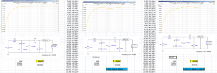
made me wonder if there could be a little gained by using a resistor after the rectifiers. Not having looked closely I assumed it goes from the rectifier to the cap but now that I think about it I doubt that is the case and some mild board surgery would be needed.
I plugged in the basic supply into DUNCAN AMPS TOOLS PS simulator and with a 29R resistor there would be halving of ripple. Of course, I have no idea how accurate this is but it does seem it could dampen pulses from the diodes.
As you go higher you get a tiny reduction in ripple but the graph looks funny. When you get to around 40R the ripple begins to increase. At 100R you are back where you started.
I do not think we have to worry about efficiency too much with this circuit.
Knowing that this is a post from someone with no fundamental knowledge of power supplies or electronics in general (I can follow the instructions and make vain attempts at synthesizing what I have seen from other circuits) I would appreciate the opinion of someone who knows.
Thanks,
The PSU board has power resistor positions from rectifier to main filter cap.
Either for mild value anti-EMI purposes rC or higher ripple reducing RC or to simply compensate for an overachieving secondary and get some filtering too.
Wow... writing so fast I almost forgot about R5 R6
Let us imagine R5 // R6 = R5*
R5* x C1 = 318uS
2187uS / 318uS = 6.87735
As I have R14 (total) = 46076 ..... then:
R5* = 46076 / 6.87735 = 6700
For R5 I have a nice pair of 6750ohm kiwames
For R6 I have a pair of 1M125 Allen bradleys
So R5* = 6750 // 1M125 = 6710 ohms (really near 6700... so I rest my case again)
Quite simple but it takes a lot of work to be able to find the right combinations using the "limited" stock values in my bin.

Hello,
I have a cartridge Ortofon 2M red.
The recommended load impedance for this cartridge is 47kOhms and 150-300pF.
The impedance of the 2SK170 is about 30pF.
Would it make sense to add a little bit of capacitance on my input load?
I have a cartridge Ortofon 2M red.
The recommended load impedance for this cartridge is 47kOhms and 150-300pF.
The impedance of the 2SK170 is about 30pF.
Would it make sense to add a little bit of capacitance on my input load?
Only your TT's cable will suffice. (The 369's Input+Miller will be more but its degenerated and cascoded also).Hello,
I have a cartridge Ortofon 2M red.
The recommended load impedance for this cartridge is 47kOhms and 150-300pF.
The impedance of the 2SK170 is about 30pF.
Would it make sense to add a little bit of capacitance on my input load?
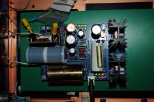
Some pics.... (Little plastic bag contains trimming C2y to be soldered)
Need to redo case gnd to cope with lo level hum.
The mini grabbers and cables aren't influential with their inductance when you trim values so closely? Or picking hum?
Not noticeable.... but I always notice a big improvement in clarity when I finally solder the caps with small legs.
Not noticeable.... but I always notice a big improvement in clarity when I finally solder the caps with small legs.
Will it be the same tonality, just more clarity?
RCruz, what case is that? It looks to be around 6cm high.
I'm having a hard time finding a nice looking 6cm case for the ssp...
I'm having a hard time finding a nice looking 6cm case for the ssp...
...But let it settle as a whole first. 48hrs play for the electrolytics to come up well. Maybe there is more resolution vs. the older set up already?
There is less gain than my old set up. It seems to be a bit lacking in the bass output as well, what could be the cause of that?
Have you got extra line gain? What is the system's gain structure? You could be missing the pre pre + MM total gain you had before or some grunge from the flicker noise previously. Could partially also be due to the Hovlands but not there to say for sure. But you should at least feel more information even if not tonally right yet. What C2Y you got? Trim it up if the tonality is light.
RCruz, what case is that? It looks to be around 6cm high.
I'm having a hard time finding a nice looking 6cm case for the ssp...
This case I salvaged from an old High End CDP from Denon, It is 1cm high and I placed a new front (10mm thick alu from Modu)
It is covered in thick copper in the inside. Quite heavy.
There is less gain than my old set up. It seems to be a bit lacking in the bass output as well, what could be the cause of that?
If done as per the pdf it should sport 62dB at 1khz.
If you lack bass, you can try increase C2y a bit. Also try lowering your cart VTA... also try a higher cart loading resistor.
If you measured your caps and resistors (in the riaa filter) you can post the values here so we can have a better look. Sometimes it R5//R6 end up with a slightly higher value then indicated in the pdf, you could notice a bump in the mid frequencies (around 1k) and that might give you the impression of lacking bass.
Attachments
Last edited:
- Home
- Source & Line
- Analogue Source
- Simplistic NJFET RIAA