Yes, dot zero. I was just coming back to fix that . . . .
Thanks for your help (again). I saw that B&D has some listed.
Thanks for your help (again). I saw that B&D has some listed.
Now it looks like surface mount stuff is the last good supply of devices.
-Chris
Hello Chris;
I could not help but wonder and think about the above statement, since i did not seem to find an equivalent for the sk170 or sk117 in the surface mount offer of the local suppliers (TME). Do you have an smd example of a sk170 equivalent for at least noise & transconductance.
Thank you!
Last edited:
For 2SK117 there is the 2SK880 stocked in Mouser's at least. Its 100mW only because SMT but identical in all other aspects.
For 2SK117 there is the 2SK880 at least. Its 100mW only because SMT but identical in all other aspects.
Thank you very much for the previous answer!
I hope i will be able to compress at this point the FSP to a stamp in a 2 layer x 2 boards design.
A dual die SMT would go a long way to provide paired stages; are there any out there matching the SK170/SK880?
As On topic, a issue that maybe anyone who built FSP has in mind ; maybe impossible since i did not seen it asked/attempted 🙂 ... so there it goes:
I tried to use a way to stabilize the TP1-TP2 voltage in the 3.5V area by replacing or using in parallel with VR1 of a thermistor(or self adjusting circuit ) that would compensate and help keep the selected voltage steady in a wider temperature interval with no tweak needed except the initial one.
Has anyone tried to match the current variation curve with a passive/active device(s) to compensate and stabilize TP1-TP2 in relation to in-chasis temperature?
I am at the point of drawing the voltage depending on temperature and the compensating resistance graph and further use it to search solutions that might come close to compensate, maybe anyone has done it or has insights!
Regards,
Calin.
The problem is no K369 and K170 SMT alternatives. Also the JFETS dissipation in some cases.
I don't remember anyone trying a thermistor. I have written enough times before about another idea though. That an active 18mA CCS could replace R13 in an attempt to stabilize the Q1 & Q2 bias current. But nobody tried. Do the input stage replica on a breadboard to see if it helps. If it does, make a little plugboard with two pins and replace R13 with it.
Did you solve that little hum problem in your combo build by the way?
Did you solve that little hum problem in your combo build by the way?
Yes my hum problem is identified. I hear it clearly at ~max amplification with no vinil playing... not much concern since with vinil ; the music is very loud at this point ... noise hearable only between tracks.
Since i do listen to music loud ... like never, is not much concern... but is there in a setup that should be perfect. And that .. irks me!
I used the link by link approach and grounding each link to find the humming source like here...
I used the FSP with no TT pluged and all i hear is white noise with no hum. So FSP is dead quiet 🙂 making my non-vanilla build of your FSP a huge success(for me)
In consequence i focused on the TT RCA wiring ; with little success ... even 0.5m of double shielded(braided and foil) microphone cable with the hot wire grounded at the TT end, and plugged into 1mV ready FSP, hums in the 50 Hz spectrum quite badly.
I'm puzzled since the same turntable does not hum when plugged into my amplifier phono stage even at max amplification(but i choose an 1mv FSP and i use it for a 2.7mV cartrige ... AT20SLA).
But hey... i'm on it ... maybe i'll be able someday to hear only white noise at max amplification.
Also the JFETS dissipation in some cases
for this jfets are magical ; use as many you want in paralel and you get more power with the added bonus of lower noise without thermal deadly loop of the hottest one.
Last edited:
That an active 18mA CCS could replace R13 in an attempt to stabilize the Q1 & Q2 bias current.
for this i will try a 2n4393 with idss 18ma as CCS
is powerful enough for the required dissipation and provides a constant 18mA
But at this point, having a CCS on q1&q2's drain or source, what good does having q3 in the signal's path?
Lift one of the two 1R resistors in the Raw PSU to see if its a channels loop.
i should be able to do well just unplugging the raw... to hear ~4 seconds the behavior on capacitor juice~120 000uF
Last edited:
for this i will try a 2n4393 with idss 18ma as CCS
is powerful enough for the required dissipation and provides a constant 18mA
But at this point, having a CCS on q1&q2's drain or source, what good does having q3 in the signal's path?
18mA is for MC config Q1 & Q2 populated. In any case measure the drop on the source resistor(s) you got in your own build and mimic their total current with a CCS instead of an R13. Add 1.8mA extra for R4. Test 4V across R4. Watch your CCS's self noise, it injects its current to the input JFETs.
Q3 is their cascoding transistor has not to do with creating constant current.
i should be able to do well just unplugging the raw... to hear ~4 seconds the behavior on capacitor juice~120 000uF
Its not the same test if the TT is making some channels loop through the preamp's chassis. Lifting the plug has to do with also testing if its a mains ground loop.
Anyone got some spare (genuine) 2SK117GR fets that you're willing to sell? I have some but the measured idss is making matching to difficult.
Cheers! 🙂
Cheers! 🙂
I do not know if these ones are 100% genuine, but they work in my circuits.
2SK170 BL, TO-92
Maybe others can comment if they are fakes or cheap copies. Schuro/Hifituning24 is a serious company, in the business for quite a long time.
2SK170 BL, TO-92
Maybe others can comment if they are fakes or cheap copies. Schuro/Hifituning24 is a serious company, in the business for quite a long time.
If the ones in your hand look the same for print fonts, body shape & features, legs details, as the Schuro's picture in that link then they should be originals.
Thank you lohk. It is just tge 2sk117's I'm after. Salas kindly suggested a possible source and i've order some last night. Just need to wait the 3 weeks for shipping.....
SUT= Step Up Transformer. Good ones are costly.
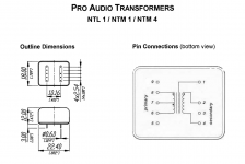
I'm playing with the original Simplistic, set up for high output MC. Recently I replaced the Denon 160 (1,6mV MC) for the Yamaha MC-9 (0,3mV MC). Therefor I installed two Neutrik NTM 1:4 step ups. Great combination on a lightweight tone arm btw. Since then I'm picking up static from telephones, on both channels. Any insights on a cure?
NTM4 - Neutrik
Hi Nick,
Success!!! I installed 10nF C0G between input returns and FSP enclosure at female RCAs with short leads, and no RF is getting in. Tested several times during this evening and it is no clicks anymore.
I left ferrite and as I mentioned, it is 3 loops of TT cable on it.
Now, it is very nice and quite background at max volume. Thank you a lot.

Alex used these caps, from cold input to chassis ground. Will any 10nF be suitable?
Hi Jaap, long time no see.
That's a split primary step up for XLR connected mics so its pin 7 may needs see ground? And is the metal shell showing continuity with the screen pin 1 or it needs an extra ground wire for the shell? Do you use shielded coaxial in general?
That's a split primary step up for XLR connected mics so its pin 7 may needs see ground? And is the metal shell showing continuity with the screen pin 1 or it needs an extra ground wire for the shell? Do you use shielded coaxial in general?
Attachments
Almost all 10nF will be suitable if its legs will be short in the installation. Its the C0G has little inductance but if used with long leads it may be beaten by them in RF grounding ability.
A long time indeed Nick. Meanwhile I enjoyed your riaa amp for nine years, how is that? 🙂
I tried several grounding variations, now it's making an extra popping sound of circa 5Hz, haha. I'll have look at daylight again.
I use RF coax for input and some low capacitance coax from an old tape deck out. Maybe it's the shielding, with the Denon it was fine.
Are there PCB's for this build?
Best regards, Jaap
- Home
- Source & Line
- Analogue Source
- Simplistic NJFET RIAA