I Measured MKP-1837 .015 1% from teabag at 14.58nF so may be my LCR meter is not so accurate... But i haven't mounted any cap for C2Y. So it's time to see now. I just didn't have enough stryroflex cap in stock
AndrewT has got me thinking.
I don't like the Idea of connecting both Phono power grounds together in the chassis. This will create a ground loop. Isn't it better to have the left and right phono to be grounded at the supply (Isolated PE) and connect the chassis together through the shield in the umbilical(non-Isolated)?
Another idea is to combine all 3 grounds at the supply and use one wire to the boards and chassis (isolated).
Last edited:
I Measured MKP-1837 .015 1% from teabag at 14.58nF so may be my LCR meter is not so accurate... But i haven't mounted any cap for C2Y. So it's time to see now. I just didn't have enough stryroflex cap in stock
Seems too much of the ones I have measured. Maybe check your LCR calibration.
About grounding a good article that worth a read http://www.diyaudio.com/forums/diyaudio-com-articles/163575-audio-component-grounding-interconnection.html
Good article but 4.3 doesn't totally cover my question. All I gathered was this:
4.3 "The alternative of connecting all of the power common lines to the star ground in the power supply chassis and then running a single shared power common wire to the amplifier suffers from Common Impedance Coupling."
So according to the article, shield connects the chassis to earth and theres an separate safety wire to ground.
Do we need two separate supply grounds (isolated by 1R) or can one be used and T'ed at the Phono boards?
Attachments
Last edited:
We want as close to dual mono as possible. The PSU for each channel has a V+ and a return. You could use a single conductor and shield as return, or you can use a twisted pair for send and return; if it's a shielded twisted pair then where do you connect the shield? The suggestion from Salas is to connect that shield to the PSU chassis.
I don't see how one would have a ground loop by connecting the two 0V lines to the ground post; that is the only place they connect.
For the main chassis I guess you have two choices: either connect it to 0V or connect it to safety earth. If the latter then should the TT ground post be isolated from the chassis? After all it connects to 0V which we isolated from safety earth at the PSU. I guess the alternative is to connect the main chassis and ground post to safety earth but not connect that to 0V reference on the amplifier boards. I wonder if anyone has tried that?
I don't see how one would have a ground loop by connecting the two 0V lines to the ground post; that is the only place they connect.
They connect at the supply. 2R is not going to separate the loop.
So after re-reading: "Each power supply should have individual power and power common lines with each power common connected to its destination in the amplifier chassis"
What I've learned,
Separate power common in umbilical is ideal because power supplies are isolated by 1 Ohm resistors.
Shield can be used as safety ground for phono chassis if gauge and connection is sufficient .
Phono PCB is only grounded by Supply (-) wire.
Arm- TT should be grounded to chassis for 0V reference and not Phono isolated ground.
Last edited:
They connect at the supply. 2R is not going to separate the loop.
Sure it is. Current will take the path of least resistance, and the DCR of the return wire should be well below 1R.
What I've learned,
Separate power common in umbilical is ideal because power supplies are isolated by 1 Ohm resistors.
Shield can be used as safety ground for phono chassis if gauge and connection is sufficient .
Phono PCB is only grounded by Supply (-) wire.
Arm- TT should be grounded to chassis for 0V reference and not Phono isolated ground.
I think your second and fourth points contradict. If you are using the umbilical shield to connect the amp chassis to safety earth, then the chassis is no longer at 0V but at safety earth potential. There should not be any current flowing through the shield so those should be at the same potential, but you have bypassed the diode/resistor network by directly connecting safety earth and PS 0V.
I don't understand what component your saying is bypassed. Are you saying the arm grounded to chassis won't be at 0V and is at safety earth potential?
So the fix for that is to connect one phono PCB ground to arm (isolated). Although one must keep the turntable ground separate to avoid EMI from the motor.
So the fix for that is to connect one phono PCB ground to arm (isolated). Although one must keep the turntable ground separate to avoid EMI from the motor.
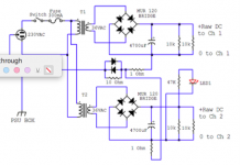
Look at the raw power supply schematic. Not only are the two 0V lines isolated from each other by a pair of 1R resistors, but the junction of those two resistors is isolated from safety earth by a network of a pair of reversed-parallel diodes (yin-yang Salas calls them) in parallel with a 10R resistor.
Now if you extend safety earth to the amplifier chassis, and connect the 0V lines, the chassis, and the TT ground wire at the ground lug, you have directly connected 0V and safety earth, bypassing that isolating network.
The way Salas recommends in the build guide is consistent and produces good results. But this is DIY and I encourage you to try alternate schemes. Just be sure to try the method suggested by Salas for comparison.
I Measured MKP-1837 .015 1% from teabag at 14.58nF so may be my LCR meter is not so accurate... But i haven't mounted any cap for C2Y. So it's time to see now. I just didn't have enough stryroflex cap in stock
Here is a French source
Polystyrène 'Styroflex' - Condensateurs audio - Composants passifs - Composants électroniques - Sommaire
Look at the raw power supply schematic. Not only are the two 0V lines isolated from each other by a pair of 1R resistors, but the junction of those two resistors is isolated from safety earth by a network of a pair of reversed-parallel diodes (yin-yang Salas calls them) in parallel with a 10R resistor.
Now if you extend safety earth to the amplifier chassis, and connect the 0V lines, the chassis, and the TT ground wire at the ground lug, you have directly connected 0V and safety earth, bypassing that isolating network.
The way Salas recommends in the build guide is consistent and produces good results. But this is DIY and I encourage you to try alternate schemes. Just be sure to try the method suggested by Salas for comparison.
Well after testing the 2 ground options:
1.-safety earth to phono chassis, phono PCB individually grounded by supply 0V
2.-supply 0V to phono PCB, phono PCB ground is put to chassis . (as per manual)
There was no audible difference. The first option is easier and more tidy.
The biggest noise maker for me was caused by the power transformer. I'm going to try to have about an 18 inch gap from any transformer for near silent operation at full volume.
Here is a French source
 thx... I know them, not too far from home, but have problem with them not so long ago. i have other french supplier 😎
Oups, i find out that i already buy some one year ago... 300pF don't know if they are good,
KS Styroflex
i wish i had remembered it earlier this WE, too late to try 😱
KS Styroflex
i wish i had remembered it earlier this WE, too late to try 😱
Is 63dB the maximum I can get with the FSP pcb? I have a problem with my current phono and cart. Too much noise (at 61 dB can't battle it) and too low gain with 0.5 mV cart @ 55 dB. So I've started contemplating FSP or/and cart swap for 0.8 mV version.
63 dB on 0,5 mV is a high nominal signal of 706 mV. Thats a more then correct consumer line level
Last edited:
The high gain version is not FSP, it's another phono.
As for SUT, I know nothing about them 🙂 It's hard to commit to something you can't control the outcome. As for ex. changing the cart for a higher output or building FSP.
As for SUT, I know nothing about them 🙂 It's hard to commit to something you can't control the outcome. As for ex. changing the cart for a higher output or building FSP.
Is 63dB the maximum I can get with the FSP pcb? I have a problem with my current phono and cart. Too much noise (at 61 dB can't battle it) and too low gain with 0.5 mV cart @ 55 dB. So I've started contemplating FSP or/and cart swap for 0.8 mV version.
The high gain version is not FSP, it's another phono.
As for SUT, I know nothing about them 🙂 It's hard to commit to something you can't control the outcome. As for ex. changing the cart for a higher output or building FSP.
SUT= Step Up Transformer. Good ones are costly.
The FSP worked straightforwardly for all its gain onfiguration options in all those builds shown here by members. Those options are not afterthoughts, they were designed in from the start. 0.5mV cartridges also work in the high gain config without objectionable THD or clipping. 57dB is more relaxed and preferable for 0.5mV when there is enough gain in the rest of a system chain. If circa 57dB presents dynamically lacking sound in a given audio system on 0.5mV cartridge already tested with another phono, then choosing the max FSP gain configuration is viable without functional problems or objectionable hiss.
- Home
- Source & Line
- Analogue Source
- Simplistic NJFET RIAA