X2 and 210Vac rating.I still have 0.01uF Vishay MKP F1778 which left from my Main AC Filter project. They rated X2. Based on your explanation, I can use these with no issues. Right?
F1778310M2DCB0 Vishay / Roederstein | Mouser
I have never seen such a low voltage X2 capacitor.
I thought all X2 were rated >=270Vac !
This may be designed for use exclusively in the USA and Japan. Certainly not in Europe, nor any other 220/240Vac supply.
Edit.
Looked up the datasheet linked in Mouser page.
It is X2 and rated to 310Vac, NOT 210Vac !!!!!!
Again Mouser have made a typo that they have not bothered to check and remove.
Last edited:
I find that Mouser and Digikey are too expensive here in the UK.
The low price they advertise bears no relation to the high price eventually paid @ the doorstep.
Try switch suppressor, or switch snubber, or switch interference suppressor.
The low price they advertise bears no relation to the high price eventually paid @ the doorstep.
Try switch suppressor, or switch snubber, or switch interference suppressor.
I remember that many guys on Felix forum complained about that typo in the past and asked Mouser to fix it. Mouser is too busy to fix such "not important" detail...
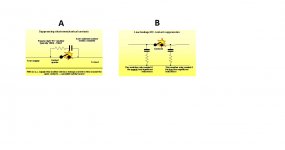
how the permissible current and voltage changes to MUCH lower values at different frequencies.
eg. @ 60Hz the 10nF is down to 1mAac. @ 1.2kHz <=100Vac
How much lower do you go? I would not run a 600mW resistor @ >300mW
eg. @ 60Hz the 10nF is down to 1mAac. @ 1.2kHz <=100Vac
How much lower do you go? I would not run a 600mW resistor @ >300mW
Last edited:
Any way, I couldn't find any RC device encapsulated in one body for arc suppression. Ton of articles, but not ready to use devices. It might be easier to build it and please help us to calculate resistor value based on 0.01uF Vishay 338 or F1778 caps.
Andrew, you created intrigue about RC snubbering across main power switches usage and did not advise about any practical parts to use there. Please close the loop.
search google.
"switch spark suppressor"
The wiki shows what the arc is
The next 3 show typical RC snubbers.
The fourth is a propriety "secret" product.
then the pics are quite informative.
"switch spark suppressor"
The wiki shows what the arc is
The next 3 show typical RC snubbers.
The fourth is a propriety "secret" product.
then the pics are quite informative.
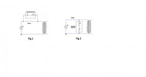
Based on what I saw, BKM is to use snubber parallel to the trany primary winding right after main switch (Fig.2). Parallel connection to the main switch (Fig.1) might introduce some small current (leakage) trough cap and resistor when switch is in open position.
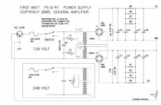
Also, I do see that Nelson Pass used 0.033uF and 10 Ohm Thermistors in his First Watt amp PSU in position pictured in Fig.2. So, beside over-themp, this thermisrors are created RC with 0.0033uF cap. So, same method as in Fig.2.
Please comment.
Also, I do see that Nelson Pass used 0.033uF and 10 Ohm Thermistors in his First Watt amp PSU in position pictured in Fig.2. So, beside over-themp, this thermisrors are created RC with 0.0033uF cap. So, same method as in Fig.2.
Please comment.
Attachments
I am not sure, but I think the two arrangements require different R values.
The Illinois link gives a pair of formulae, but does not say they are different R, so maybe they are the same.
http://www.google.co.uk/url?sa=t&rc...w-Kz4fFYozCkSQg&bvm=bv.95515949,d.ZGU&cad=rja
The Illinois link gives a pair of formulae, but does not say they are different R, so maybe they are the same.
http://www.google.co.uk/url?sa=t&rc...w-Kz4fFYozCkSQg&bvm=bv.95515949,d.ZGU&cad=rja
That previous post has a link copied from Google. Is there a way to simplify the link to take one straight to the pdf page?
No. it is completely different.same method as in Fig.2.
The Pass capacitor is straight across the L&N of the mains. It is an interference attenuator. It combines with the source and cable impedance to create a low pass filter.
The CL60, one on each 110/120Vac primary, is a permanently in place soft start for the transformer. Better to arrange an automatic time delayed bypass of the added resistance of CL60 in the primary circuit .
Last edited:
That previous post has a link copied from Google. Is there a way to simplify the link to take one straight to the pdf page?
Yes.
Attachments
After our discussion and after reading relevant articles, I desired that it is portably better not to use any arc suppression snubbers or caps on our low current devices.. They might create more troubles than to solve issues. They more needed on high current relays when on/off rate is high. Nick, do you use these snubbers on your builds or just dissent quality main power on/off switch is good enough ?
Sent from my iPhone using Tapatalk
Sent from my iPhone using Tapatalk
Salas,
With my just completed build I get 56.8 volts off the PS rails. I seem to remember that 55.5 volts is the max? I can adjust to get the right voltages for TP1. Should I put in a resistor to bring the raw voltage below 55.5?
Thanks.
With my just completed build I get 56.8 volts off the PS rails. I seem to remember that 55.5 volts is the max? I can adjust to get the right voltages for TP1. Should I put in a resistor to bring the raw voltage below 55.5?
Thanks.
55.5V is the theoretical limit not to burn Q2x. It does not always burn on edge of its spec but better cut 5V-10V with 3W power resistor between bridge and smoothing capacitor. It will also make an EMI filter and will bring Q1x sink's temperature down.
- Home
- Source & Line
- Analogue Source
- Simplistic NJFET RIAA