All charts I have seen about various capacitance types in semiconductors datasheets are versus voltage. Haven't seen VS frequency. Maybe experts know something else.
I can not answer that question but i can shed some light on a typical misconception.
The Miller capacitance stays always the same, cascoded or not. It just does not multiply with the voltage gain because the cascode device does the voltage amplification.
Also that cascodes have more speed is not so simple as it seems. What goes up is the gain in the lower frequencies but not gain-bandwidth, that stays the same. If you feed back or degenerate a cascode distortion goes down because of that gain advantage.
You really need Willy Sansens´s "Analog Design Essentials" when you want to go into the details.
The impedance that drives Q3 is R5/R6 i parallel. Yes, in the audio range that does not make any trouble. There is not much on vinyl records over 50kHz anyway besides cracks from dirt and blemishes.
Ok, there is the output impedance of the first stage in series and R7 in parallel, in total somewhat around 6kOhm driving 30pF.
If it is non cascoded common source then the above equation (#8025) gives the full Miller phenomenon AFAIK. With a shielding device above it being a common base BJT or a common gate Jfet I have seen that source degeneration further limits the capacitive phenomenon along THD at high swing since the shielding device is not perfect. Early voltage, Hfe, Cob and such stuff should be limiting perfect shielding for infinite bandwidth. Right?
Hi JoachimOk, there is the output impedance of the first stage in series and R7 in parallel, in total somewhat around 6kOhm driving 30pF.
Where did you get the 30pF figure from ?
So this should be average value for input capacitance of k170 cascoded second stage ?
I am trying to tune my Riaa calculator for this new design.
I am trying to tune my Riaa calculator for this new design.
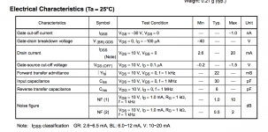
No, this is only indicative IMO. The K170 Vds under the BF245C or J310 was 2.7-3V in breadboard test. That gets you to 35pF Ciss. Crss goes to 10pF at that Vds. If it was without cascoding it could be around 230pF Miller effect with the gain and Rs used. I hope for 4 to 5 times reduction with JFET cascoding in this non perfect world, and it remains to be measured. With a BJT and higher Vds like in first stage it can go closer to elimination and nearer to just Ciss.
Salas, i will publish a graph from Sansen that shows what is going on in general.
Nice.
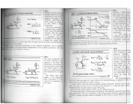
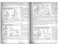
0255 shows that G/BW is not affected so when i trust Bruno Putzeys the speed does not go up when G/BW is the measure of speed. Se " The F Word" in Linear Audio.
The open loop gain falls of with 6dB octave usually so it depends on the feedback factor,
degeneration or GFB come to mind. What is clear is that the cascode gives more gain but also lower open loop bandwidth. In total, given the same resulting gain the cascode is lower in distortion because we win more gain then we loose open loop bandwidth.
degeneration or GFB come to mind. What is clear is that the cascode gives more gain but also lower open loop bandwidth. In total, given the same resulting gain the cascode is lower in distortion because we win more gain then we loose open loop bandwidth.
- Home
- Source & Line
- Analogue Source
- Simplistic NJFET RIAA