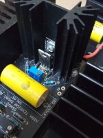
SSHV2 measurements with bench PSU 9VDC and + connected to 0 at output, Q1 VGS 2,2V Q2 VGS 0,43V
Max. CCS TP 42mA
N.B. Desoldered both Q1 & Q2 to test with Peak Atlas DCA55 and both are health.
N. B. 2 Desoldered and tested both diodes & the 500R trimmer all OK
Max. CCS TP 42mA
N.B. Desoldered both Q1 & Q2 to test with Peak Atlas DCA55 and both are health.
N. B. 2 Desoldered and tested both diodes & the 500R trimmer all OK
Bad news, with bench PSU SSHV2 CCS works as expected but when I use the real PSU only reach 40mA...so something not good with PSUDII!!
As I understand there is nothing in SSHV2 to límit CCS mA if I can get the desired mA with bench PSU and not with real in circuit PSU?
Maybe oscillation due to other wiring with your test raw psu? Does it seem hotter than working for just 40mA? That would be a clue.
SSHV2 CCS not more hotter when tested with bench PSU.
I guess no oscillation because no other wiring testing raw PSU.
I guess no oscillation because no other wiring testing raw PSU.
Not tested because it's a little bit difficult to measure but surely is lower with raw PSU.
Last edited:
Well Salas definitely is the PSU, the SSHV2 is feeding a cascode CCS as anode load, so to be sure isn't the SSHV2 I disconnected the SSHV2 and connected directly the raw PSU to the cascode CCS as anode load to see whats the max. mA can I get and summing both channels are 36mA clearly raw PSU doesn't reaches the 60mA that needs the SSHV2 to power the cascode CCS as anode load for 20mA for each channel.
Do you know if increasing capacitance at raw PSU could increase these 36mA to 60mA needed?
Do you know if increasing capacitance at raw PSU could increase these 36mA to 60mA needed?
I use a 100K bleeder resistor between the raw PSU output & the load or regulator could be the problem?
This SSHV2 was regulating a couple of 4P1L headphone amp from raw PSU B+ 340V to 200V after SSHV2 output, TP measured 1,1V so 110mA, load 80mA without any problem.
KO when connected to a raw PSU B+ 340V with a load of 34mA, load are a couple of cascode CCS set to 17mA each channel working without issues without SSHV2 direct raw PSU to both cascode CCS.
Any idea was happening Salas?
I forgot to tell you that I use in place of Q3 IRF840 the SIHP8N50D-GE3 mosfet N-CH 500V 8.7A TO-22 because when made the IRF840 was out of stock & with long delivery time so you told me to use the SIHP as equivalent.
Last edited:
This question is probably been asked 'at nauseam' but I just finished putting the raw dc board together, I endup with 280V on a 5k ohm load and I am trying to regulate down to 200V @ 60mA load. Is the 80V drop excessive?
thank you!
thank you!
I guess only enough power dissipation heatsinks.
280V @ 5K = 56mA
I guess no problem 4mA more, if so increase 5mA more at input cascode CCS and remember 20mA more for SSHV2 self consumption.
280V @ 5K = 56mA
I guess no problem 4mA more, if so increase 5mA more at input cascode CCS and remember 20mA more for SSHV2 self consumption.
- Home
- Amplifiers
- Power Supplies
- Simplistic mosFET HV Shunt Regs
