FYI After checking the datasheet again I noticed that the Vgs threshold for the tsmc is 6v instead of 4v for the irf840.
Vgs Q3/R8 creates Q4 Q5 Ic (bias current). Typically 4V/1.8k=2.2mA. Little on its own but dissipation W is Ic * HVout. About half of it on each TO-126 transistor. To keep same Ic and dissipation with a 6V Vgs Mosfet R8 is 2.7k.

Thanks Salas!
So the change is to increase the drop across R8 to get the Vgs up to 6V that the new mosfet needs. At the same time keeping the same 2.2ma through q4/5 so 6/0.0022=2.7k. Dissipation on r8 goes from 9 to 12 mW.
So the change is to increase the drop across R8 to get the Vgs up to 6V that the new mosfet needs. At the same time keeping the same 2.2ma through q4/5 so 6/0.0022=2.7k. Dissipation on r8 goes from 9 to 12 mW.
Last edited:
A conducting Mosfet imposes certain Vgs across R8 anyway, so we size R8 properly to derive our bias current goal for the cascode driver transistors.
Using SSHV2 powering Valve Itch set to 50mA,Vin SSHV2 moving up & down slowly between 332,88-335,23V is confirming oscillation?
After SSHV2 Vout moving up & down slowly between 315,45-315,93V
After SSHV2 Vout moving up & down slowly between 315,45-315,93V
Last edited:
If jumping slowly its just thermal cycle of the JFET. Blow air from your mouth on the JFET as a test and it should move output voltage even more.
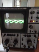
Oscillation hunt is AC coupling for 10x probe input on the scope, 5-10mV sensitivity vertical, horizontal sweep from 1mS to 10uS, looking for flat line, no bug waveforms like distorted sine or distorted triangular etc.
10mV 0.2ms 10x probe
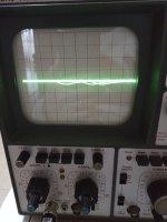
Measured taken between SSHV2 and cascode CCS probe + and probe - to GND, right pic without probe - to GND
Measured taken between SSHV2 and cascode CCS probe + and probe - to GND, right pic without probe - to GND
Attachments
Last edited:
On first look the system seems oscillating. It could also be about interference.
It can be doing it with the particular CCS load but if measuring SSHV2 alone with just dummy load, not doing it.
In any case repeat with short gnd spring accessory to make sure its not interference on the probe's gnd crock wire.
It can be doing it with the particular CCS load but if measuring SSHV2 alone with just dummy load, not doing it.
In any case repeat with short gnd spring accessory to make sure its not interference on the probe's gnd crock wire.
Without GND crock wire using new probe with short GND spring no oscillation at SSHV2 output, probe set x10 calibrated, measurements done with 5 & 10mV/cm and between 1ms to 10us
When used SSHV2 with CCS was with a lot of less voltage and current for 26 (3-5mA & 150V) now is very different for 801A 20mA 234V
Definitely there is something no good using togheter SSHV2 and cascode CCS or Ale's Moglia aka Bartola hybrid mu-follower (gyrator) so active load reacts very bad with SSHV2 so if I want to use SSHV2 only with anode resistor load, I guess no problem SSHV2 with anode choke load or line output transformer.
Did you use the new Mosfet?
Did something blowup again?
Are you talking about a siberian 4 -type setup?
Maybe it's a type of hall-of-mirror between the the two CCS in series. Don't know if it's the right way to call an oscillaition like this.
For all intents an purposes the SSHV2 has already all the PSSR you will ever want.
Did something blowup again?
Are you talking about a siberian 4 -type setup?
Maybe it's a type of hall-of-mirror between the the two CCS in series. Don't know if it's the right way to call an oscillaition like this.
For all intents an purposes the SSHV2 has already all the PSSR you will ever want.
Last edited:
- Home
- Amplifiers
- Power Supplies
- Simplistic mosFET HV Shunt Regs