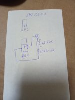
On a breadboard put a DN2540 with a 10R between its Gate and Source. Provide it 1.5V DC from AAA battery. + through DMM Ameter (series mode) to Drain, - to G trough a 100R-1K gate stopper. Use the 10A input not to kill the DMM's mA range fuse in a mishap. That shall give you an idea where the DN2540 sample can go for max mA in this circuit when the CCS trimmer is at Zero and T.P. resistor is 10Ω. Use it for Q2. Select a Q1 with same or more mA capability.

Thanks Salas, the same for Ixys IXTP01N100D, IXTP08N100D2 & IXCP10M45S?
It's correct the attached schematic?
Could I use to set cascode CCS as anode load?
It's correct the attached schematic?
Could I use to set cascode CCS as anode load?
Attachments
Last edited:
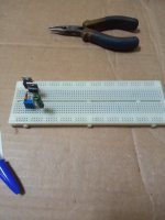
A test circuit picture for clarity.
Even more than 1.5V VDS Q2 can be found in an actual SSHV2. Would help mA further.
T.P. resistor can be lowered to 1Ω (1mV=1mA) to help max mA if near but not enough.

Even more than 1.5V VDS Q2 can be found in an actual SSHV2. Would help mA further.
T.P. resistor can be lowered to 1Ω (1mV=1mA) to help max mA if near but not enough.
Same thing, maybe somewhat different B+. 1.5V is indicative. Types and samples differ.Thanks Salas, the same for Ixys IXTP01N100D, IXTP08N100D2 & IXCP10M45S?
*If you want to avoid Ameter you can read mV across TP resistor and interpret to mA.
But with Zero TP resistor you absolutely need Ameter and reading is IDSS for that VDS.
But with Zero TP resistor you absolutely need Ameter and reading is IDSS for that VDS.
Put the 100R inside to the gate, at the node with 10R.It's correct the attached schematic?
I w
I'll follow your schematicPut the 100R inside to the gate, at the node with 10R.
Maybe you can. Try it to see what mA you read and predict, then how it translates when as CCS in the actual amp.
Measured also the lower cascode 2SK3557-7-TB-E
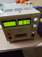
1,5V = 23,9mA
2V = 24,8mA
2,5V = 25,2mA
3V = 25,5 mA
1,5V = 23,9mA
2V = 24,8mA
2,5V = 25,2mA
3V = 25,5 mA
No but togheter the Ixys can deliver 40mA with 10V of B+.
I need 25mA per channel for the 801A.
I will not use SSHV2 because the input cascode CCS only reach 40mA less 20mA for SSHV2 left only 20mA so 10mA per channel.
I wanna be sure isn't the SSHV2 that give enough current so I will test with CCS without SSHV2.
I need 25mA per channel for the 801A.
I will not use SSHV2 because the input cascode CCS only reach 40mA less 20mA for SSHV2 left only 20mA so 10mA per channel.
I wanna be sure isn't the SSHV2 that give enough current so I will test with CCS without SSHV2.
Last edited:
- Home
- Amplifiers
- Power Supplies
- Simplistic mosFET HV Shunt Regs