
Hello guys,
if i understand right - to test SSHV2 and tune it to a proper voltage we need to calculate the dummy load resistor according to a current and voltage needed (that is o.k.. and clear)...
then we connect s+ and f+ together and that connection point we connect to one leg of the dummy resistor... the other leg goes to a connection where s0 and f0 join together??? right? or is ti becauses wires need to be twisted together and f wires need to be twisted together to form a sense???
i am a bit unclear - just wanted to confirm..
Last edited:
I have a couple of quick questions, I almost built the boards BUT I would like to make a few substitution to use what I have here and avoid making a Mouser order:
in the RC 0.47u and 3ohms instead of 0.33/1.8 combination, 5uF instead of 10uF for the big cap and 2x75k in place of 2x68k.
Could that work?
@Merlin
what's the deal with your 40mA limit? I need 60mA at 200V and man says up to 100mA (maybe 80 + the 20mA headroom).
in the RC 0.47u and 3ohms instead of 0.33/1.8 combination, 5uF instead of 10uF for the big cap and 2x75k in place of 2x68k.
Could that work?
@Merlin
what's the deal with your 40mA limit? I need 60mA at 200V and man says up to 100mA (maybe 80 + the 20mA headroom).
Should still work, does not look unstable with those Zobel values. 5uF just means less noise filtering mainly in the subsonic region. Does not affect otherwise.I have a couple of quick questions, I almost built the boards BUT I would like to make a few substitution to use what I have here and avoid making a Mouser order:
in the RC 0.47u and 3ohms instead of 0.33/1.8 combination, 5uF instead of 10uF for the big cap and 2x75k in place of 2x68k.
Could that work?
CCS max setting depends on individual IDSS of Q2 in combination with how much VGS is enveloping it by Q1. Usually capable of achieving circa 100mA max setting in this circuit.
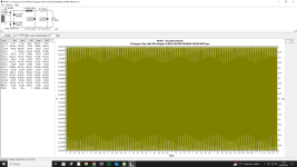
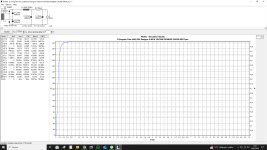
Yes, but it's really weird that PSUDII doesn't show any kind of problem....Cool, you mean the raw voltage supply?
Last edited:
Well Duncan said to check all connections if are OK or not because PSUDII simulation is ok, he checked with LTSpice with same results.
What's the formula to calculate?CCS max setting depends on individual IDSS of Q2 in combination with how much VGS is enveloping it by Q1. Usually capable of achieving circa 100mA max setting in this circuit.
- Home
- Amplifiers
- Power Supplies
- Simplistic mosFET HV Shunt Regs