By trying more Q1 samples in the cascode, some produce higher VGS some lower for same mA passing.
OK thanks, BTW it seems Ixys IXTP08N100D & IXTP08N100D2 not in stock at Mouser, Digikey, Farnell.
Both IXTP08N100D measures real circuit cascode VGS 2,1V
Vin both channels 353,5V
Vout Left channel 212,56V
Ia Left channel 12,46mA
Vout Right channel 216,92V
Ia Right channel 12,88mA
I used as lower cascode 2SK3557-7-TB-E both channels with the same measured 25mA or a little more
Vin both channels 353,5V
Vout Left channel 212,56V
Ia Left channel 12,46mA
Vout Right channel 216,92V
Ia Right channel 12,88mA
I used as lower cascode 2SK3557-7-TB-E both channels with the same measured 25mA or a little more

I'm sorry Salas, that's I have with others CCS not the breadboard.Both IXTP08N100D measures real circuit cascode VGS 2,1V
Vin both channels 353,5V
Vout Left channel 212,56V
Ia Left channel 12,46mA
Vout Right channel 216,92V
Ia Right channel 12,88mA
I used as lower cascode 2SK3557-7-TB-E both channels with the same measured 25mA or a little more
Last edited:
I'm sorry Salas, that's I have with others CCS not the breadboard.Right channel reach max. 14mA
Left channel reach max. 14,9mA
Last edited:
Breadboard reach 40mA but can't go lower than 39mA, used 5K trimmer to set the current an 10R to measure it, the drop voltage across the CCS is only 17V. N. B. Used in real circuit.
The not breadboard CCS drops the voltage across the CCS 125V and only reach 13mA.
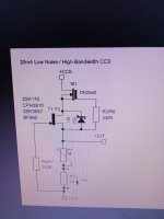
The CCS breadboard is exactly the same like attached schematic, only change gate stoppers are 470R.
The not breadboard CCS drops the voltage across the CCS 125V and only reach 13mA.
The CCS breadboard is exactly the same like attached schematic, only change gate stoppers are 470R.
Attachments
Last edited:
Sorry Salas it seems than changing the 1R for 10R to measure the current was bad connected, I will try and let you know.
I changed the 2SK3557-7-TB-E with more mA and got 3mA in real circuit, tomorrow I will look for a couple of Ixys IXTP08N100D2 waiting to reach the target of 20mA.
Salas comparing different VGS (off) is the best Ixys IXCP10M45S with a minimum of 5V?
IXTP08N100D2 min. 2V max. 4V
IXTP08N100D min. 2,5V max. 5V
DN2540 min. 1,5V max. 3,5V
IXTP08N100D2 min. 2V max. 4V
IXTP08N100D min. 2,5V max. 5V
DN2540 min. 1,5V max. 3,5V
When using such D-Mosfets at relatively few mA vs their full capability, Vgs should manifest higher but relatively still close to Vgs (th) "threshold". Its the point where they just turn on/off. It takes two to three times that voltage to pull max current. Its also an indicator of more IDSS i.e. the more -Vgs it takes to shut a Mosfet off, the stronger drain current it should pull when Vgs is zero. Because samples differ, predict at about mid value between min max of the stronger values type.
Thanks Salas, I guess the problem isn't the upper device because this morning I tested with a couple of IXTP08N100D2 and with the strongest 2SK3557-7-TB-E that I have with more than 25mA and can reach the target of 20mA, next atempt will be selected BSH111BNK.
- Home
- Amplifiers
- Power Supplies
- Simplistic mosFET HV Shunt Regs