According to upper claims, meaning all output transistors in A-class are way out of their optimal operating conditions, producing unavoidable self distortions .
I know only what I've read here on the forum, but I think I grasp the logic:
In the lengthy discussions, it's been referred to as optimal class AB bias - optimal in the sense that it minimizes crossover distortion. In class A (or while operating in class A), it's not relevant, because there is no crossover until you reach the limit of class A.
As someone mentioned earlier in this thread, with heavy class A bias, the crossover point is not reached until the output is at a correspondingly high level. At that point, the crossover distortion is relatively less, as a fraction of the output. So there seems to be a trade off to be made. Maybe there is a point where the quality curves (more class A, vs. optimal AB bias) cross.
Mentioned in this thread is the effect of operating temperature as an independent factor. Another possible trade off - the combination of heatsink, emitter resistor, output device number, etc..
Also mentioned is that current across the device may be an independent factor in sound quality, or that a minimal current value should be met.
So my logical (but not experienced conclusion) would be that for maximum energy efficiency with good sound, the optimal drop across Re is an important consideration. Otherwise, maybe not so much?
Sheldon
edit: This, by the way, is why I chose 0R1 emitter resistors in my build - more current to reach optimal Re, more class A. Is it the right choice? Don't know.
Last edited:
It is not quiescent current what is important in case of BJT OPS but the voltage between emitter resistors. Look in Audio Power Amplifier Design Hanbook by D. Self.
D. Self explained it in his book quite clearly. Different values for EF OPS and different for CFP OPS. Chapter 5. The Output Stage.
So do-I, and 0.22 when two paralleled devices, 0.33 when 3.This, by the way, is why I chose 0R1 emitter resistors in my build
Hi Esperado,
I am not sure whether reducing the current through parallel devices would have the same effect as optimising the current for lowest distortion in each device.
Even when I parallel device I still run 180 mA bias through each of them and the results are both measurable and audibly different than running them at half or one third the optimum bias current.
I think this is exactly what the Cat is implying. The 300 mA bias seems high but it may be only 150 mA per device which may be close to optimum and requires Re of around 0.17 Ohm for 25mV drop.
Last edited:
D. Self explained it in his book quite clearly. Different values for EF OPS and different for CFP OPS. Chapter 5. The Output Stage.
Short summary? 🙂
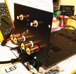
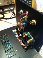
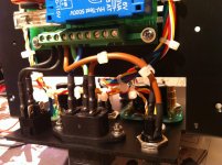
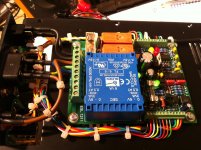
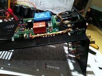
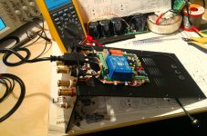
SSA Soft Start utility PCB and all external parts connected today, except input/output terminals which will be wired with channel modules later on. This kind of case module is easy to wire because every connection is made before final assembly, parts are accessible and can be easy to service if needed. 😎
Attachments
Last edited:
Short:
All types of outputs shows different gainsteps over current through load.
Qaussi types are not symmetrical.
Cfp. Shows a very narrow deltacurrent for this gainstep.
Mosfet is more or less identical but you have an extra parameter (vgs for a certain current...)
Multiple devices in parallel makes the step more soft.
The more steep this gainstep is the faster should the VAS stage be.
It is less demanding to pair that way and the total quiescent current stay the same...Hi Esperado,
I am not sure whether reducing the current through parallel devices would have the same effect as optimising the current for lowest distortion in each device. .
For FETs, i stay at 150mv each...
Last edited:
Next Size
LC, I'm planning another one, which using darlington EF.
Brought few good heatsink (0.5°C/Watt),
300VA 2 x 18 VAC secondary transformer, which should not be himalayas anymore.
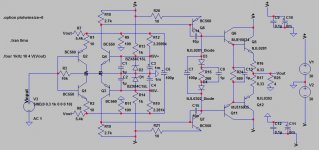
By using BC550/560 as VAS with 5mA Iq, the gain, ft, Cob is good, only weakness is no heatsink attachment, but I have BP100 (thermal conductive adhesion tape). The peak dissipation is about 0.35W only, should be no problem.
The thing that i'm not sure about is C14/15 (compensation), according to 1st attachement simulation, 10pF seems to be best. But I wanted to use 2SA1707/2SC4487 as driver as in 2nd attachment, which I have no SPICE model, can't be simulated.
Hope everyone could give me suggestion for improvement.
Edit : I thought about NJL3281/1302 or NJL4281/4302 (and I have them), they seems to need to have slightly higher Iq for better ft response, maybe I will use in my next Class A project.
Also 0281/0302 have lower output capacitance. Should I have 2 pairs of it at OPS (paralleling for better performance) ?
About the previous SSA little I done, maybe because the 1707/4487 I replace in VAS, it oscillate at small scale and deteriorate the sound because there is no Cdom (and its ft is too good) ?
LC, I'm planning another one, which using darlington EF.
Brought few good heatsink (0.5°C/Watt),
300VA 2 x 18 VAC secondary transformer, which should not be himalayas anymore.
As per attached, aiming for Vpp to 20+, which about 80-100W into 4 ohm.*AA53002-018* Page 12 *
http://www.acmepowerdist.com/pdf/amveco_catalog.pdf#page=12
By using BC550/560 as VAS with 5mA Iq, the gain, ft, Cob is good, only weakness is no heatsink attachment, but I have BP100 (thermal conductive adhesion tape). The peak dissipation is about 0.35W only, should be no problem.
The thing that i'm not sure about is C14/15 (compensation), according to 1st attachement simulation, 10pF seems to be best. But I wanted to use 2SA1707/2SC4487 as driver as in 2nd attachment, which I have no SPICE model, can't be simulated.
Hope everyone could give me suggestion for improvement.
Edit : I thought about NJL3281/1302 or NJL4281/4302 (and I have them), they seems to need to have slightly higher Iq for better ft response, maybe I will use in my next Class A project.
Also 0281/0302 have lower output capacitance. Should I have 2 pairs of it at OPS (paralleling for better performance) ?
About the previous SSA little I done, maybe because the 1707/4487 I replace in VAS, it oscillate at small scale and deteriorate the sound because there is no Cdom (and its ft is too good) ?
Attachments

Last edited:
For me the final value of compensation should judged by ear.
I think 10pF is a very good starting point before you listen.
mike
I think 10pF is a very good starting point before you listen.
mike
Hm.... so I should test between values ? kinda troublesome if you ask me, just add another 10pF in parallel to become 20pF ?
^^
^^
Member
Joined 2009
Paid Member
This, by the way, is why I chose 0R1 emitter resistors in my build - more current to reach optimal Re, more class A. Is it the right choice? Don't know.
I really like what I saw in Roenders amplifier - he used 3 output pairs with low Re values to ensure about 2W of output in Class A. It needs some good heatsinking, its Class A afterall, but it deals nicely with the cross-over distortion. And even more than that, the lower current swings through the output pairs means lower distortion overall. The improvement is large.
Only downside with 0R1 is less thermal stability - good heatsinks and Vbe multiplier placement is probably a lot more important.
Hm.... so I should test between values ? kinda troublesome if you ask me, just add another 10pF in parallel to become 20pF ?
^^
sure and 5pF might be worth a try also
For me the final value of compensation should judged by ear.
By ears or by oscilloscope? I'm not convinced if ears can help here.
The scope is essential because it defines a sensible band within which the amp works OK, i.e. no oscillation on the one hand and not slowed down too much on the other.
Using square waves into 8R + 100nF is my preferred method.
Within that band the ears can decide which value is preferable.
In my experience a small change in value can make a big subjective difference and it is not hard to choose the which value works for you.
Having done it a few times you might build an idea of what scope performance your ears prefer but not using your ears at all means you miss out on a significant amplifier "voicing" opportunity.
Last edited:
well..... according to the simulation, the least compensation is 10pF in my case, will try soon,
may I know what is your standard to choose the value ? using ear, simulation, or oscillioscope ?Mine went up to 18pF but from 6.8pF was acceptable.
- Status
- Not open for further replies.
- Home
- Amplifiers
- Solid State
- Simple Symetrical Amplifier