My method: compensate CR for a flat response in sinus with your charge. (no peak at the end of the bandwitch).By ears or by oscilloscope? I'm not convinced if ears can help here.
Then, work on square waves at 100kHz, and filter the input for no overshoot.
Then, you can filter more the input *with your ears*.
haha, nice idea X.x You sounds like using oscillioscope is making life difficult X.x
I assume the safe value is between 50pF to 10pF ?
I assume the safe value is between 50pF to 10pF ?
Thanks guys, this is really a new thing for me!!
What kind of sound perception that you expect from increasing the capacitance from the minimum? Doesn't "the smaller the better" apply here?
What kind of sound perception that you expect from increasing the capacitance from the minimum? Doesn't "the smaller the better" apply here?
You should start with something that damps any peak on the hi band response first, then more pF ''curves'' the Q of the response's dive edge, smooths out possible edges on square wave is another indication. You should listen by changing for something like tuning a best controlled loudspeaker transient behavior. You know, not too flabby not too edgy and resolute.
You should start with something that damps any peak on the hi band response first, then more pF ''curves'' the Q of the response's dive edge, smooths out possible edges on square wave is another indication. You should listen by changing for something like tuning a best controlled loudspeaker transient behavior. You know, not too flabby not too edgy and resolute.
Wow!! From your explanation it seems to me that 5pF difference may give such a huge impact! I have never been aware of this possibility so once I get no more than 22pF (and it must be polystyrene cap or at least silver mica) I have never paid attention to the sound.
Thanks guys, this is really a new thing for me!!
What kind of sound perception that you expect from increasing the capacitance from the minimum? Doesn't "the smaller the better" apply here?
we're choosing a path between two undesirable characteristics.
If an amp is under compensated there is a tendency towards ringing which can be excited by the signal. This ringing has absolutely no harmonic relationship to the signal so we can regard it as adding noise into the amplifier. You could build a beautifully quiet power supply but if the amp has this ringing tendency the benefit is lost because the amp itself is generating noise and this self generated noise can really spoil the sound.
If an amp is over compensated it drains the life out of the music and the foot tapping "live" quality is lost.
With a nice fast design like SSA the tendency for ringing is minimised so the cure for any instability does not spoil the "live" sound very much.
I think Andre runs his SSA with no compensation. The fact that this is even possible is quite remarkable but based on previous experience I think I will prefer a little compensation when I finally manage to finish my SSA !
Edit: I learned this stuff from JLH from his articles from the 1960's ! I know he regarded it as one of the most important elements in building good sounding amps because he specifically mentioned this when he replied to a letter I wrote him about one of his designs. I keep his letter to me - my memento of an audio legend 🙂
Last edited:
I think Andre runs his SSA with no compensation.
I always reduce the compensation cap from commercial amps. I believe that commercial amps tend to be overcompensated for security reason.
The last time I upgraded my opamp based amplifier (last month), I reduced miller cap from 47pF to 22pF, remove 100pF capacitors from the input, and removed 220pF between opamp input pins. No oscillation.
I'm looking forward to LC comment regarding his decision to leave the cap completely out of the circuit (as I thought it should).
Do you measure them also? How about THD20 and SQwaves?
Unfortunately no. I have retired my o'scope. Just a special radio for that purpose. And ears to perceive sound improvement 😀
The last time I upgraded my opamp based amplifier (last month), I reduced miller cap from 47pF to 22pF, remove 100pF capacitors from the input, and removed 220pF between opamp input pins. No oscillation.
The tendency for ringing can be there way before the onset of oscillation so for me oscillation is not the issue.
Pushing square waves into 8R + 100n just amplifies the phenomena to a scale where the ringing is blatent and is easily observable on a scope.
The Theory says that the human ear can simultaneously hear a 70db range of volumes so if we are listening to a 1V signal we only need 0.3mV of spurious ringing to hear the difference. Is that measurable ? Not by me.
But I would guess that most people could hear if that ringing was eliminated.
For me, if all else is equal, it is the difference between good & sublime
Last edited:
Not necessary a good idea. The law is:remove 100pF capacitors from the input, and removed 220pF between opamp input pins.
1- Try to get the fastest amp you can.(open loop bandwidth or slew-rate).
2- Reduce the signal slew-rate at the input as much as you can: More margin, less TIM.
It is important too with digital signal where the bandwitch (20khz with a huge slope ) is not correlated with the slew rate. (you can have 20Kz square waves in the same time. Reason why some find digital sounds agressive ?
Remember that at 20kz, the signal you get is mainly distortion products. And you will get more natural treebles with a slow decrease after 16 Khz (depending on your tweeters, of course). I never use super tweeters any more, but drivers with a high power/dynamic capacity.
Member
Joined 2009
Paid Member
...and it must be polystyrene cap or at least silver mica...
As far as I remember, the real silver mica caps behave a bit differently, the dielectric is slightly more effective when used in a Cdom type position than some other caps so you may find that you can use a lower valued cap if it is silver mica.
From the very few projects I've completed, I find that the ear is the best instrument for tuning the compensation caps (phase lag especially but also phase lead) once you are within the envelope of good stability. I have found that square wave testing is very useful, but it can result in over compensation. Some signal sources have rising edges that are brutally fast and not that realistic, plus you are designing for DIY not a commercial amp which may be 'abused' in terms of what kind of nasty loads get hooked to the speaker terminals. Over compensation kills sonics.
just my 2c.
Last edited:
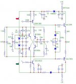
Here's what I've got. I'm not sure if this thermaltrak approach is practical. The VAS current is very sensitive to the VAS device temperature. Ideally they require a very efficient heatsink, but with very low thermal mass, so the equilibration temperature is reached quickly. Hard to do in practice. It takes quite a few minutes to stabilize. This with a pretty small heatsink - about 1mm thick by about 2cm square.
The 180k resistor from VAS base to common speeds up the initial temperature rise, but not the overall time.
I get nice ringing, so some compensation adjustments are needed (not shown on schematic are 15pf from base to collector). But I don't want to spend the effort unless I can get this thing to settle much faster.
Attachments
Here's what I've got. I'm not sure if this thermaltrak approach is practical. The VAS current is very sensitive to the VAS device temperature.
You were contemplating some Vbe mult. between the drivers and/or TO-92 DN2540s instead of trimmers, weren't you?
- Status
- Not open for further replies.
- Home
- Amplifiers
- Solid State
- Simple Symetrical Amplifier