Wind your own OT. 800 turns on the core already. $45 Like 40 turns for the secondary. Circlotron 3200 Ohm primary.


Last edited:
Well, an output impedance of 3200 Ω in a Circlotron transforms into 3200 * 4 = 12800 Ω in a conventional PP amplifier with the same tubes operating at the same conditions. No that useful, is it 😉 ? Hence, decreasing the secondary turns number to 20 would give a more useful primary impedance of 800 Ω.
But what about that 50-400 Hz frequency range written on that toroid?
Best regards!
But what about that 50-400 Hz frequency range written on that toroid?
Best regards!
OTL amplifiers are not necessarily big, heavy and complicated - see mine some posts above !
A good inspiration for a simple, stable, reliable and efficient circuit is to consider Mr Julius Futterman's orginal patent and circuit filed in 1953 :
https://patents.google.com/patent/US2773136A/en
That's exactly from where I started for designing and building my U-OTL6080 :


T
A good inspiration for a simple, stable, reliable and efficient circuit is to consider Mr Julius Futterman's orginal patent and circuit filed in 1953 :
https://patents.google.com/patent/US2773136A/en
That's exactly from where I started for designing and building my U-OTL6080 :
T

This is not pure OTL amp since use simple autotrafo on output , it is vintage schematic and is from famous Russian designer Krylov ,
Warning !!! , main isolation transformer 220V~/220V~ is not shown in the schematic and is apsolute Mandatory !!!
Warning !!! , main isolation transformer 220V~/220V~ is not shown in the schematic and is apsolute Mandatory !!!
Attachments

Yes, and with an isolation transformer you can replace that lonely 1N5408 diode by a bridge rectifier.
Best regards!
Best regards!
Ah, I would have expected that you'd converted that well known OTL design by P. Dickie and J Makovsky with three 6082's from series heater to parallel supply:A good inspiration for a simple, stable, reliable and efficient circuit is to consider Mr Julius Futterman's orginal patent and circuit filed in 1953 :
https://patents.google.com/patent/US2773136A/en
That's exactly from where I started for designing and building my U-OTL6080 :
http://www.audiodesignguide.com/otl/6082.gif
Best regards!
Agreed , think that the simplest way is to start with some standard main isolation toroid transformer 235V~/220V/220V~ , where mising 6,3V~/3A winding can be added manually , also output autotrafo can be some very small toroid type since it is not loaded with any DC component .Yes, and with an isolation transformer you can replace that lonely 1N5408 diode by a bridge rectifier.
Best regards!
Best Regards !
OTL amplifiers are not necessarily big, heavy and complicated - see mine some posts above !
A good inspiration for a simple, stable, reliable and efficient circuit is to consider Mr Julius Futterman's orginal patent and circuit filed in 1953 :
https://patents.google.com/patent/US2773136A/en
That's exactly from where I started for designing and building my U-OTL6080 :
View attachment 1259512
View attachment 1259513
T
Your builds are works of art!
re: Kay Pirinha
Yes, I forgot the 4X in Circlotron mode. But the secondary needs -twice- as many turns, ie. 80 turns, to bring the primary down to 800 Ohm (for the 3200 Ohm P-ct-P equiv.).
These current transformers are rated for some accuracy in measuring main line current. So a limited freq. range will be specified. Having the extension to 400 Hz probably means the core has a thin lamination, just like an audio one. Capacitance in the core winding has to be minimized for accuracy versus freq, so the winding is likely a long progressive wound one around the core. Just like a Plitron! And your primary is rated for 5 Amps! You probably do want the high turns current transformers for tube use.
With one of these fixup OTs on the OTL (think of "postprocessing") you'll only need a couple of 6L6s for output tubes. Big power and heat savings.
I ordered a couple of the cores to try out, I will test the freq. response.
I know some will not stomach a post processing xfmr for their OTL, so then you'll just have to brute force it:

Well, an output impedance of 3200 Ω in a Circlotron transforms into 3200 * 4 = 12800 Ω in a conventional PP amplifier with the same tubes operating at the same conditions. No that useful, is it 😉 ? Hence, decreasing the secondary turns number to 20 would give a more useful primary impedance of 800 Ω.
But what about that 50-400 Hz frequency range written on that toroid?
Yes, I forgot the 4X in Circlotron mode. But the secondary needs -twice- as many turns, ie. 80 turns, to bring the primary down to 800 Ohm (for the 3200 Ohm P-ct-P equiv.).
These current transformers are rated for some accuracy in measuring main line current. So a limited freq. range will be specified. Having the extension to 400 Hz probably means the core has a thin lamination, just like an audio one. Capacitance in the core winding has to be minimized for accuracy versus freq, so the winding is likely a long progressive wound one around the core. Just like a Plitron! And your primary is rated for 5 Amps! You probably do want the high turns current transformers for tube use.
With one of these fixup OTs on the OTL (think of "postprocessing") you'll only need a couple of 6L6s for output tubes. Big power and heat savings.
I ordered a couple of the cores to try out, I will test the freq. response.
I know some will not stomach a post processing xfmr for their OTL, so then you'll just have to brute force it:
Last edited:
Ah, I would have expected that you'd converted that well known OTL design by P. Dickie and J Makovsky with three 6082's from series heater to parallel supply:
http://www.audiodesignguide.com/otl/6082.gif
Best regards!
Hi @Kay Pirinha !
Yes indeed, the Dickie and Makovsky OTL circuit is well known - I have the complete article somewhere on my PC, but never experimented it, because with more NFB loops, more stages, it is more complex than the Futterman 1953-1956 original patent circuit, which I took as the basis of my design...
My U-OTL has one power transformer which provide the requested high and low voltages from 230 or 240VAC 50Hz that we have here :
Of course, I would not have used the mains directly ! Not because it doesn't works (and it works well, I tested it), but for basic insulation safety reasons, in order to avoid any possible electric shock with the mains network.
T
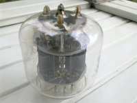
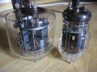
And Russian original counterpart to US-7242 ; 12C42C , triple low Rp triode , formed from 3 triode , 120 degr. distributed in one glass bulb , ideal for OTL amps ,🙂
and also simmilar tube 654 from development process .
and also simmilar tube 654 from development process .
Attachments
Yes, twice the secondary turns number, of course, to get the primary impedance down to a quarter. Must have been still sleeping this morning 😵 ...
Btw, where fron do you know the primary turns number? And which maximum output power would you guess with this kind of transformer?
Best regards!
Btw, where fron do you know the primary turns number? And which maximum output power would you guess with this kind of transformer?
Best regards!
Am I right that this tube is more or less three halves of a 6C33C?And Russian original counterpart to US-7242 ; 12C42C , triple low Rp triode , formed from 3 triode , 120 degr. distributed in one glass bulb
Best regards!
Here are the square waveforms that my U-OTL shows for 10W RMS Output / 12.65V / 16 Ohms :


Rather a good performance for a tube amplifier with NO global NFB loop... 😎
Thank you Mr Futterman ! 😉
T
Rather a good performance for a tube amplifier with NO global NFB loop... 😎
Thank you Mr Futterman ! 😉
T
re: Kay Pirinha
I'm guessing that the 600V tag rating is saturation V for the winding, not sure. (@ 50 Hz?) Typically want to run below 0.7 saturation for linearity.
The 10 KV should be the isolation V to the mains bus-bar. Educated guessing. Could check the Cat No. at the manufacturer or the class rating standard.
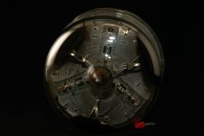
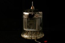
From searching the internet: 8RL-4002 seems to be a GE equivalence #, Transformer ID dimension is 3.25 inch, class 0.3 is 0.3% accuracy for utility billing, Rating Factor of 0.8 (20% derated from max??? no explanation yet), current ratio 4000:5 4000 Amps on mains will give 5 Amps to the metering, these things get installed with a shorting strap across the winding initially to prevent electrocution - haven't seen a max V listed yet, but could be that 600V #. From picture scaling: 3.25 inch ID gives 5.75 inch OD
The Ratio 4000:5 Amp rating on the tag gives away the 800 to 1 turns. (4000/5 = 800:1 ) 5 Amps rating for the winding, 4000 Amps for the mains.Btw, where fron do you know the primary turns number? And which maximum output power would you guess with this kind of transformer?
I'm guessing that the 600V tag rating is saturation V for the winding, not sure. (@ 50 Hz?) Typically want to run below 0.7 saturation for linearity.
The 10 KV should be the isolation V to the mains bus-bar. Educated guessing. Could check the Cat No. at the manufacturer or the class rating standard.
From searching the internet: 8RL-4002 seems to be a GE equivalence #, Transformer ID dimension is 3.25 inch, class 0.3 is 0.3% accuracy for utility billing, Rating Factor of 0.8 (20% derated from max??? no explanation yet), current ratio 4000:5 4000 Amps on mains will give 5 Amps to the metering, these things get installed with a shorting strap across the winding initially to prevent electrocution - haven't seen a max V listed yet, but could be that 600V #. From picture scaling: 3.25 inch ID gives 5.75 inch OD
Last edited:
The GE datasheet for the 8RL-402 current xfmr says 80 VA. Winding resistance of 0.973 Ohm. The 0.8 # is a continuous thermal rating factor, whatever that is. Hard to believe 800 turns would be 0.973 Ohm, but probably needed for 5 Amps. Taking 75 VA and dividing by 5 Amp would give 15V. (@ 50 or 60 Hz ) The graphs on page 2 do show it flat lining around 25 V. UH-OH, this may NOT work for a tube OT!! Two toroids would handle 50V. Would also work for higher frequencies. At 400 Hz, should work for approx. 8 x 25V or 200V.
Last edited:
Could use one Current Xfmr to make a spot welder. Or twenty of them to make a 750 Watt tube OT.
Last edited:
What about a stock 2 * 115/24 Vac toroid wired as an autoformer according to the sketch in #44? When loaded with 8 Ω, it would give a primary impedance of about 800 Ω, ideal for a Philips design with a pair of EL86/PL84/UL84's. I don't know that much about stray inductances in mains toroids, but would give it a try anyway.
Best regards!
Best regards!
- Home
- Amplifiers
- Tubes / Valves
- Simple OTL for beginners?