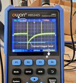
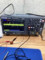
There are two, possibly three, mistakes in the experimental setup of #2,660
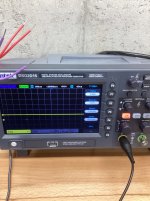
A. The sweep speed is far too slow; I expect to see something between 2 microseconds per division and 20 microseconds per division. Not 1000 usec/div
B. The scope is triggered on the rising edge; I expect to see it triggered on the falling edge. See "Triggering the Oscilloscope" on page 12 of the Quasimodo design note.
C. (??) I can't tell whether the blue horizontal line is, or isn't, the trigger voltage level. It's very close to the correct trigger level.
_
Attachments
Okay, was my error, sorry.
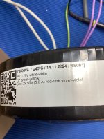
Now, the first measurement of a 20 VA donut - in this position I get 7,1 ohms for Rs.
Is the graph okay?

Now, the first measurement of a 20 VA donut - in this position I get 7,1 ohms for Rs.
Is the graph okay?
Many thanks Mark for the quick reply, I noticed my errors at the same time you wrote me.There are two, possibly three, mistakes in the experimental setup of #2,660
A. The sweep speed is far too slow; I expect to see something between 2 microseconds per division and 20 microseconds per division. Not 1000 usec/div
B. The scope is triggered on the rising edge; I expect to see it triggered on the falling edge. See "Triggering the Oscilloscope" on page 12 of the Quasimodo design note.
C. (??) I can't tell whether the blue horizontal line is, or isn't, the trigger voltage level. It's very close to the correct trigger level.
_
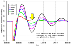
Please twist the trimmer just a little bit to make the second bump (the downwards bump) maybe 1/2 of a vertical division tall, post a photo, and report the trimmer resistance which gave that photo. It may be that your resistance is perhaps a bit too low. After the photo requested here, we will know the answer.
In pictures: dial the trimmer until the second bump (yellow arrow) on your scope trace, strongly resembles the green line in Figure 10. Take a photo then report the trimmer resistance.
_
In pictures: dial the trimmer until the second bump (yellow arrow) on your scope trace, strongly resembles the green line in Figure 10. Take a photo then report the trimmer resistance.
_
Attachments
Thanks again, Mark!
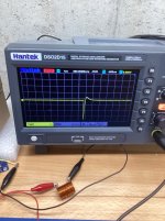
Now, using the correct setting I get the following graphs.
1: without snubber pot
2: with 8,5 ohms Rs
It's my first real measurement, so the inevitable question: does it look right?
Many thanks in advance.


Now, using the correct setting I get the following graphs.
1: without snubber pot
2: with 8,5 ohms Rs
It's my first real measurement, so the inevitable question: does it look right?
Many thanks in advance.
Hi folks,
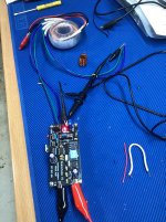
Today I received two AN-0218 transformers that I intend to use with the Zen Mod Balanced Preamp. I ran the Quasimodo jig on them and got surprisingly different results. The picture on the left looks like what I expected. Rs measures approximately 32 ohms on both secondaries. But the second transformer pictured on the right has a curve that looks different on the scope. Rs is approximately 128 ohms.
Any idea why they are so different?
Thanks,
John
Attachments
I don't expect the 20VA Antek's to be dramatically different than the 10VA Antek's measured in the Quasimodo results (ONLY) thread, post #163.
Double check that you haven't accidentally swapped Cx and Cs
Double check that all transformer primary wires are firmly shorted together. See QM design note Figure 13.
Double check that all secondary-not-under-test wires are shorted together
Double check that you get the same result when you swap the two secondary wires going into the green Euroblox connector marked TRANSFORMER
Double check that you're triggering on the falling edge; the pictures appear to show that you're NOT.
Double check that you're setting the triggering level appropriately: about -5.0 volts when using a 9V battery. (hint: look at top right. It's not good)
Remove the transformer wires and replace with a fixed inductor. Remove trimmer. Double check that you get a waveform with LOTS of ringing that decays pretty darn slowly
Last edited:

Mark, I must be doing something wrong (I'm new to oscilloscopes). Capacitors C2 and C3 have the correct values in them. The dual primaries are all shorted together. The secondary not under test is shorted. I am now triggering on falling edge. The trigger level is set at -5.0 V. I'm using a linear supply set to 9.0 VDC. Probe and scope are set to 10X. Reversing the wires of the secondary under test has no impact.
I am not getting any recognizable waveform at these setting when I force a trigger.
I haven't tried attaching any inductor yet. I have a small coil that was a trial inductor for the Wolverine build. I trust that it will serve the purpose.
Any suggestions would be appreciated,
John
I am not getting any recognizable waveform at these setting when I force a trigger.
I haven't tried attaching any inductor yet. I have a small coil that was a trial inductor for the Wolverine build. I trust that it will serve the purpose.
Any suggestions would be appreciated,
John


I had the same issue, until I played with the time (your setting is 200 us, try it with 1-2-5 us) and input voltage range, I think yours may be too high.
Don't be afraid to turn the voltage and time division knobs. You can't hurt anything. I find it works best to turn the time division until I get something then adjust the voltage. Of course, sometimes I get nothing with that, so change the voltage a couple up or down and try again, rinse and repeat if necessary. I notice your scope has an auto set, also try that, although on mine it doesn't work with the quasimodo, I have to manually set it.
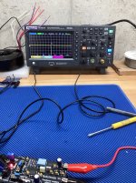
I continue to be flummoxed. I went back to my 500 Va Toroidy transformer with 50 V secondaries. The scope is set to trigger on falling edge. R5 is set to about 22 ohms which seemed to get me the correctly damped curve when I measured it a couple of weeks ago. Now all I can dial in is what you see in the picture below. I'm doing something wrong.
John
John
Attachments
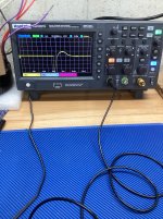
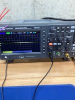
Ok, now I am at 1us. The wave form I observe (picture below) looks more like what I expect, but it keeps jumping around. I had to stop the scope to capture this image. It's impossible to adjust the trimmer with the wave form moving back and forth. I don't understand what's causing this.
Trigger is set to falling edge. Probe is set to AC coupling and probe and scope are set to 1X.
John
Trigger is set to falling edge. Probe is set to AC coupling and probe and scope are set to 1X.
John
Attachments
Where do you have the second channel trigger hooked up? Don't quite remember, but it's in Mark's write-up where to place the trigger pickup. Seem to remember on the board next to the MOSFET to get the cleanest trigger. you may also need to tweak your trigger level.
- Home
- Amplifiers
- Power Supplies
- Simple, no-math transformer snubber using Quasimodo test-jig