This is great series on transformer snubbers.
I did not see a example for a high voltage secondary like used in tube B+ power supplies. Perhaps I missed them as there is a lot of information in the thread.
So her goes my example for a high voltage center tapped transformer for tube circuits. I hope it is useful to some.
I have noted for some time that when solid state diodes are used for the high voltage secondary in tube amplifiers that artifacts from the diode switching shows up in the filament supply of the tubes and if you look very carefully is also in the distortion products of the amplifier.
I suspect the ringing couples across all transformer windings and then easily crosses the heater/cathode capacitance and into the audio path.
While I have never heard these artifacts I simply never liked the fact that they were there and seemed a decent argument in favor of tube based rectification.
The artifacts show up even when high speed diodes are used. It seems even a fast diode is glacial in speed compared to a vacuum tube rectifier.
If these artifacts can be banished by proper snubbers that opens a lot of flexibility in rectification for a high voltage supplies so I thought to give this method a go.
The impedance of a high voltage secondary should be much higher than a low voltage secondary like used for solid state amplifiers.
This suggested to me smaller snubber capacitor values for a high voltage winding may be acceptable.
Smaller value high voltage capacitors are of interest to me for a few reasons.
First, the size of a a 600V AC 150nF capacitor is significant. For example the low cost 150nF 600V AC Kemit pat number R76QN31505050J is about 1" long and 3/4" wide. This is pretty big when you need two for a center tapped transformer setup.
Second, a high value snubber capacitor will draw more current at very high voltages and so snubber resistor dissipation will rise. The reactance of a 150nF capacitor at 60Hz is 1/(150e-9 * 2 * 3.14 * 60) = 17.68k
I am using a Hammond 278X transformer and the no load secondary voltage is 432V each side of the CT.
Worst case each snubber capacitor will draw 24.88mA of reactive current. That represent about 10% of the current for the total transformer VA rating from the secondary. Seems too high a cost in current for the snubber function.
Yes the total current level will drop when the snubber resistor in included but will still be unacceptably high in my opinion.
So I set about snubbing the secondary of my Hammond 278X transformer using smaller capacitors and here is where I got to.
Cx (injection) I used a 2.2nF low dielectric loss 2KV ceramic capacitor that is designed specifically for in switch mode and class D amplifiers for rising edge control. A film capacitor designed for high AC voltage would also be a good choice like is used in electronic lighting ballasts but I had the ceramic part in my "bins".
I would suggest caution in the selection of the capacitors for use directly across a high AC voltage as many (most) capacitors will not tolerate that application unless designed specially for such a application.
With a 2.2nF capacitor for Cx I noted the frequency of the ringing was 20.83KHz.
So for the snubber Cs (snubber) I used a 4.7nF capacitor that will have a reactance of 1.626K at 20.83KHz.
I know that 4.7nF is far from the application note's guidlines for having Cs about 10 times the size of Cx however keeping the capacitors small in value was what I was aming for. I will admit I know not if my low ratio of Cx to Cs will create a sensitivity in tolerance but as the values are being tested on the actuall transforer sample to be use this seemed a accetable risk.
I shorted the primary and on half of the secondary to the CT lead on the transformer as the application note suggests.
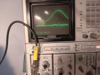
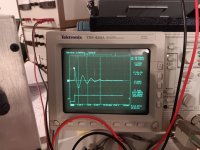
Tuning for the value of Rs I came up with 3.9K and that produced a nice looking damped waverform. This also suggested the reactance of Cs at 1.6K in series with a Rs of 3.9k shoud result in reasonable damping as resistance domanates the damping network.
Finally I added snubber networks on both sides of the centertap secondarry and tested the damping again.
The results to my eye looks very accetable and a huge improvement over a undamped transformer HV secondary.
Thank you Mark Johnson for your excellent contrubution to the comunity.
I did not see a example for a high voltage secondary like used in tube B+ power supplies. Perhaps I missed them as there is a lot of information in the thread.
So her goes my example for a high voltage center tapped transformer for tube circuits. I hope it is useful to some.
I have noted for some time that when solid state diodes are used for the high voltage secondary in tube amplifiers that artifacts from the diode switching shows up in the filament supply of the tubes and if you look very carefully is also in the distortion products of the amplifier.
I suspect the ringing couples across all transformer windings and then easily crosses the heater/cathode capacitance and into the audio path.
While I have never heard these artifacts I simply never liked the fact that they were there and seemed a decent argument in favor of tube based rectification.
The artifacts show up even when high speed diodes are used. It seems even a fast diode is glacial in speed compared to a vacuum tube rectifier.
If these artifacts can be banished by proper snubbers that opens a lot of flexibility in rectification for a high voltage supplies so I thought to give this method a go.
The impedance of a high voltage secondary should be much higher than a low voltage secondary like used for solid state amplifiers.
This suggested to me smaller snubber capacitor values for a high voltage winding may be acceptable.
Smaller value high voltage capacitors are of interest to me for a few reasons.
First, the size of a a 600V AC 150nF capacitor is significant. For example the low cost 150nF 600V AC Kemit pat number R76QN31505050J is about 1" long and 3/4" wide. This is pretty big when you need two for a center tapped transformer setup.
Second, a high value snubber capacitor will draw more current at very high voltages and so snubber resistor dissipation will rise. The reactance of a 150nF capacitor at 60Hz is 1/(150e-9 * 2 * 3.14 * 60) = 17.68k
I am using a Hammond 278X transformer and the no load secondary voltage is 432V each side of the CT.
Worst case each snubber capacitor will draw 24.88mA of reactive current. That represent about 10% of the current for the total transformer VA rating from the secondary. Seems too high a cost in current for the snubber function.
Yes the total current level will drop when the snubber resistor in included but will still be unacceptably high in my opinion.
So I set about snubbing the secondary of my Hammond 278X transformer using smaller capacitors and here is where I got to.
Cx (injection) I used a 2.2nF low dielectric loss 2KV ceramic capacitor that is designed specifically for in switch mode and class D amplifiers for rising edge control. A film capacitor designed for high AC voltage would also be a good choice like is used in electronic lighting ballasts but I had the ceramic part in my "bins".
I would suggest caution in the selection of the capacitors for use directly across a high AC voltage as many (most) capacitors will not tolerate that application unless designed specially for such a application.
With a 2.2nF capacitor for Cx I noted the frequency of the ringing was 20.83KHz.
So for the snubber Cs (snubber) I used a 4.7nF capacitor that will have a reactance of 1.626K at 20.83KHz.
I know that 4.7nF is far from the application note's guidlines for having Cs about 10 times the size of Cx however keeping the capacitors small in value was what I was aming for. I will admit I know not if my low ratio of Cx to Cs will create a sensitivity in tolerance but as the values are being tested on the actuall transforer sample to be use this seemed a accetable risk.
I shorted the primary and on half of the secondary to the CT lead on the transformer as the application note suggests.
Tuning for the value of Rs I came up with 3.9K and that produced a nice looking damped waverform. This also suggested the reactance of Cs at 1.6K in series with a Rs of 3.9k shoud result in reasonable damping as resistance domanates the damping network.
Finally I added snubber networks on both sides of the centertap secondarry and tested the damping again.
The results to my eye looks very accetable and a huge improvement over a undamped transformer HV secondary.
Thank you Mark Johnson for your excellent contrubution to the comunity.
Attachments

Last edited:

Did you then observe a change in 'artifacts' in an audio amp, as a before-after assessment of deploying the HT winding snubbers?
I presume you also were shorting the 5V and 6V3 heater windings on that transformer too?
I presume you also were shorting the 5V and 6V3 heater windings on that transformer too?
Artifacts with HV supplies are imho more related to abruptness of the winding's conduction current when it reaches zero. For ss diode rectification, the winding current 'hits' zero abruptly, as the winding voltage only reduces by less than 1V as the ss diode transitions from fully on to off. In contrast, a valve diode increases its on resistance significantly as the winding voltage reduces the last few volts before current stops being conducted, and that transition is a lot more benign, and causes a much lower voltage disturbance in the winding leakage inductance (the 'bell' part of the quasimodo effect).The artifacts show up even when high speed diodes are used. It seems even a fast diode is glacial in speed compared to a vacuum tube rectifier.
With a capacitor input supply the diodes supply current to the load near the peak of the SIN output waveform.For ss diode rectification, the winding current 'hits' zero abruptly, as the winding voltage only reduces by less than 1V as the ss diode transitions from fully on to off.
With solid state diodes when the voltage across the SS diode reverses there is a large and abrupt reverse current spike due to the diode "Reverse Recovery Time"
This abrupt reverse current spike causes the transformer leakage inductance to "ring".
Diode Reverse Recovery Time causes solid state diodes to turn off AFTER the voltage has already reversed across the diode and a reverse current has started to increase and flow in the diode. The result is a large reverse current spike in the transformer secondary winding while the diode leaves the conduction state that rings the leakage inductance in the transformer like a bell.
This ringing of the leakage inductance in the transformer is the source of the distortion artifacts I see in the form of short bursts of energy at a 120Hz rate.
Solid state diodes actually only turn off after the diode voltage has reversed and reverse current is flowing backwards in the diode.
Vacuum tube rectifiers do not have a similar reverse current spike issue when the applied voltage is reversed.
For a simple example of Diode Reverse Recovery Time, see... https://www.electrical4u.com/reverse-recovery-time-of-diode/
The ringing is actually a resonance between the leakage inductance and the winding capacitance. A pure inductor cannot ring itself.
If you have a battery operated, portable oscilloscope with no connection to the AC mains and no connection to the Protective Earth wire in the AC mains socket, then (because a battery powered scope is isolated and floating, unconnected to any circuit "ground") you can use it to view the waveforms of your actual transformer secondary circuit in your actual audio gear. You can observe whether ringing occurs in bursts which occur every (1 / 120 = 8.3333 milliseconds) -- or not. You can observe whether circuit modifications XX or YY or ZZ change the ringing, making it either better or perhaps worse.
Be careful when doing this: your actual audio gear contains lethal voltages, and if your probe slips it could be very dangerous.
Be careful when doing this: your actual audio gear contains lethal voltages, and if your probe slips it could be very dangerous.
Bluesystems, ss diode reverse recovery is much more noticeable for low voltage ss amps, but I'd suggest not so significant for valve amp related applications due to a few factors including the secondary winding resistance, lower peak current level, and broader conduction portion of time.
Mark's quasimodo tester rings the bell in a very aggressive and rapid manner, and somewhat similar to how you would see ss diode reverse recovery waveforms and testing portrayed, so as to make each effect easily identifiable and measureable. Mark even reported on the performance of a variety ss diodes, but that too was in a special circuit that allowed performance differences to be more easily compared.
A typical valve amp power supply does not provide the conditions for reverse recovery to be a significant effect, as the conditions to force the diode into such a situation are orders of magnitude below what a manufacturer will test/specify for, and what you will see in reference papers and explanations on the effect. The effect is I suggest barely identify when comparing different ss diodes - I set up one set of comparisons between 1N4007 and UF4007 and just observed a change in noise floor signature with a low noise soundcard and REW spectrum. My thoughts on the topic are in this linked discussion paper in section 3 : https://dalmura.com.au/static/Power supply issues for tube amps.pdf
Ciao, Tim
I fully accept that in some (many?) cases the noise generated by diode recovery in the high voltage DC section of tube amplifiers and the resulting ringing may not be measurable in conventional tube amplifier THD results.
The total energy involved can be quite low and in my amplifier sample using a Hammond 273BX transformer was a 38KHz pulse about 80uS long.
At a 120Hz rate this is a duty cycle less than 1%.
This noise is certainly difficult to detect in wide bandwidths measurements as the very short duration of the ringing noise pulse results in the total energy involved being very low.
As well any measurement system needs to have wide bandwidth as much of the noise energy seems to be very high in frequency, several decades above 20KHz.
This noise may well be difficult to detect in amplifiers with a THD residual above 0.1% as the low total energy level of the noise will drop under the amplifier residual THD.
I noted this noise while working to drive the THD levels of my last amplifier design to lower levels at low frequencies. It was there that I saw a odd pulse that was not fixed to the test frequency but drifted along the measured residual THD waveform.
I had not noted this noise pulse in higher frequency measurements (1KHz) as it becomes smeared across the scope screen and lost in the noise floor.
When I selected a test frequency that was in sync with the line frequency the noise pulse became more visible. At the time I did not worry too much thinking this was just power line noise and as the total THD was pretty low at less than 0.1% I just moved on.
After reading Marks thread I thought to revisit this amplifier design and the noise I had seen.
Lab results
Note the diodes used in testing were of a fast recover type.
My test setup is a bit unconventional and perhaps open to disagreement. In order to make the general noise floor and high frequency noise more evident I removed the low frequency harmonic components of the residual THD with a 400Hz filter in order to make the high frequency pulse and amplifier noise floor more evident.
This means the THD numbers represent only the amplifier noise floor and THD harmonics above 400Hz (about the 8th harmonic and above) and do not represent conventional total THD numbers. I have from past experience found the level and nature of a amplifier's noise floor spectrum can be a important issue of the overall amplifier listening experience.
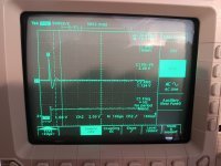
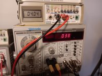
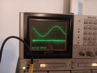
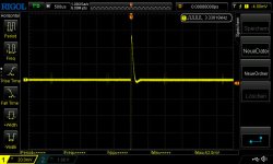
I first tested the amplifier THD at 60Hz and 2.8 watts into 8 ohms as it was built. The attached scope pictures show the noise pulse and noise plus THD around 0.038%
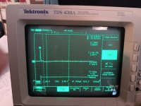
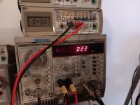
Then I retested the amplifier under the same condition using a very low noise external bench supply in place of the amplifiers internal high voltage power supply. The diodes were disconnected for this test. The noise pulse was now completely absent in the residual THD and total noise pulse and noise plus THD had dropped to about 0.022%. Seems a significant reduction.
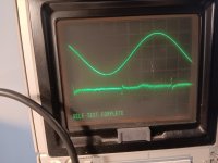
The third test was after adding two snubber networks one on each side of the center tap of the high voltage secondary consisting of Cx=2.2nF Cs= 4.7nF Rs=2.4K.
Retesting the amplifier showed the noise pulse was still present in the residual THD on the scope screen but at a far lower level that seemed to have no effect on the measured total noise pulse and noise plus THD of 0.019%. The residual THD was now comparable to that measured with a external lab high voltage supply and one half of the level before the snubbers were added. Again this seems a worthwhile reduction.
What does any of this mean in terms of audibility? I will leave that question to be debated and answered by others.
I have however experienced in designing high power class D amplifiers for subwoofers that even very small levels of harmonic distortion energy at very high harmonic frequencies compared to the fundamental and well below measurable levels can be surprisingly audible. Think 0.01% of high order harmonics buried in a subwoofer driver's 3% to 5% second and third harmonic distortion being very audible as a small fuzz sound, sounding much like a mechanical defect or air leak in the driver. This experience leads me to be less quick to say this or that level of THD or noise is inaudible.
For me the snubbers are clear improvement in measurable performance that is easy and low cost to implement.
It seems reasonable to me to add snubbers to any high or low voltage DC power section in any audio amplifier as a standard design measure.
Again thanks to Mark for the insight and opportunity to learn.
The total energy involved can be quite low and in my amplifier sample using a Hammond 273BX transformer was a 38KHz pulse about 80uS long.
At a 120Hz rate this is a duty cycle less than 1%.
This noise is certainly difficult to detect in wide bandwidths measurements as the very short duration of the ringing noise pulse results in the total energy involved being very low.
As well any measurement system needs to have wide bandwidth as much of the noise energy seems to be very high in frequency, several decades above 20KHz.
This noise may well be difficult to detect in amplifiers with a THD residual above 0.1% as the low total energy level of the noise will drop under the amplifier residual THD.
I noted this noise while working to drive the THD levels of my last amplifier design to lower levels at low frequencies. It was there that I saw a odd pulse that was not fixed to the test frequency but drifted along the measured residual THD waveform.
I had not noted this noise pulse in higher frequency measurements (1KHz) as it becomes smeared across the scope screen and lost in the noise floor.
When I selected a test frequency that was in sync with the line frequency the noise pulse became more visible. At the time I did not worry too much thinking this was just power line noise and as the total THD was pretty low at less than 0.1% I just moved on.
After reading Marks thread I thought to revisit this amplifier design and the noise I had seen.
Lab results
Note the diodes used in testing were of a fast recover type.
My test setup is a bit unconventional and perhaps open to disagreement. In order to make the general noise floor and high frequency noise more evident I removed the low frequency harmonic components of the residual THD with a 400Hz filter in order to make the high frequency pulse and amplifier noise floor more evident.
This means the THD numbers represent only the amplifier noise floor and THD harmonics above 400Hz (about the 8th harmonic and above) and do not represent conventional total THD numbers. I have from past experience found the level and nature of a amplifier's noise floor spectrum can be a important issue of the overall amplifier listening experience.
I first tested the amplifier THD at 60Hz and 2.8 watts into 8 ohms as it was built. The attached scope pictures show the noise pulse and noise plus THD around 0.038%
Then I retested the amplifier under the same condition using a very low noise external bench supply in place of the amplifiers internal high voltage power supply. The diodes were disconnected for this test. The noise pulse was now completely absent in the residual THD and total noise pulse and noise plus THD had dropped to about 0.022%. Seems a significant reduction.
The third test was after adding two snubber networks one on each side of the center tap of the high voltage secondary consisting of Cx=2.2nF Cs= 4.7nF Rs=2.4K.
Retesting the amplifier showed the noise pulse was still present in the residual THD on the scope screen but at a far lower level that seemed to have no effect on the measured total noise pulse and noise plus THD of 0.019%. The residual THD was now comparable to that measured with a external lab high voltage supply and one half of the level before the snubbers were added. Again this seems a worthwhile reduction.
What does any of this mean in terms of audibility? I will leave that question to be debated and answered by others.
I have however experienced in designing high power class D amplifiers for subwoofers that even very small levels of harmonic distortion energy at very high harmonic frequencies compared to the fundamental and well below measurable levels can be surprisingly audible. Think 0.01% of high order harmonics buried in a subwoofer driver's 3% to 5% second and third harmonic distortion being very audible as a small fuzz sound, sounding much like a mechanical defect or air leak in the driver. This experience leads me to be less quick to say this or that level of THD or noise is inaudible.
For me the snubbers are clear improvement in measurable performance that is easy and low cost to implement.
It seems reasonable to me to add snubbers to any high or low voltage DC power section in any audio amplifier as a standard design measure.
Again thanks to Mark for the insight and opportunity to learn.
Attachments
-
 as-built-no-snubber-scope.jpg469.3 KB · Views: 139
 -
 as-built-no-snubber-thd.jpg347.6 KB · Views: 141
 -
 external hv supply-scope.jpg328.2 KB · Views: 137
 -
 external hv supply-thd.jpg423.2 KB · Views: 121
 -
 snubber 2.2nf.4.7nf-2.4k.scope.jpg466 KB · Views: 129
 -
 snubber 2.2nf.4.7nf-2.4k-thd.jpg498.2 KB · Views: 128
 -
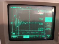
 ringing-before-2.2nF.4.7nF-2.4k.snubbers.jpg430 KB · Views: 137
Last edited:
Very nice work @Bluesystems ! Congratulations.
I agree that the cost is so low, why on earth NOT use snubbers.
I agree that the cost is so low, why on earth NOT use snubbers.
You're using exactly the same test gear as me! SG505/AA501 and 7854. The only thing to beat it would be an Audio Precision analyzer, but that needs exceptionally deep $45k pockets.I fully accept that in some (many?) cases the noise generated by diode recovery in the high voltage DC section of tube amplifiers and the resulting ringing may not be measurable in conventional tube amplifier THD results.
The total energy involved can be quite low and in my amplifier sample using a Hammond 273BX transformer was a 38KHz pulse about 80uS long.
At a 120Hz rate this is a duty cycle less than 1%.
This noise is certainly difficult to detect in wide bandwidths measurements as the very short duration of the ringing noise pulse results in the total energy involved being very low.
As well any measurement system needs to have wide bandwidth as much of the noise energy seems to be very high in frequency, several decades above 20KHz.
This noise may well be difficult to detect in amplifiers with a THD residual above 0.1% as the low total energy level of the noise will drop under the amplifier residual THD.
I noted this noise while working to drive the THD levels of my last amplifier design to lower levels at low frequencies. It was there that I saw a odd pulse that was not fixed to the test frequency but drifted along the measured residual THD waveform.
I had not noted this noise pulse in higher frequency measurements (1KHz) as it becomes smeared across the scope screen and lost in the noise floor.
When I selected a test frequency that was in sync with the line frequency the noise pulse became more visible. At the time I did not worry too much thinking this was just power line noise and as the total THD was pretty low at less than 0.1% I just moved on.
After reading Marks thread I thought to revisit this amplifier design and the noise I had seen.
Lab results
In my setup I have the ability to send the measured THD residual result to a small speaker/amplifier as I find it can be interesting to just listen to how the THD involved "sounds".
So I listened today to the filtered THD residual. Not sure why I did not think to do this first.
Without the snubbers there is a loud and clear buzz well above the random noise floor that beats against the 60Hz test tone in the filtered THD residual result.
With the suubbers in place the buzz is still there but now deep down in the noise floor and just audible above the rush of the noise floor.
So the snubber will stay and be added to any future project.
I have a older Audio Precision analyzer as well but I dislike the overhead of messing with the computer for most lab work.The only thing to beat it would be an Audio Precision analyzer
As well when chasing a noise issue especially power line stuff having that huge noisy computer as part of your test setup is not working in your favor.
KISS
The AP is great when used for sweep or comparative measurements but the old school Teck wins with me for just getting basic lab work done quickly and accurately.
The old 7854 has plugin options that allow audio measurements the digital guys have never even thought of. Add to that the port on the back lets you connect a amplifier and "hear" as well as see what you are measuring. It's a boat anchor but a wonderful instrument.
Last edited:
Very interesting, and cool!With the suubbers in place the buzz is still there but now deep down in the noise floor and just audible above the rush of the noise floor.
I have a friend who has the original Audio Precision (System 1) analyzer. And like you it seldom comes out to play.I have a older Audio Precision analyzer as well but I dislike the overhead of messing with the computer for most lab work.
As well when chasing a noise issue especially power line stuff having that huge noisy computer as part of your test setup is not working in your favor.
KISS
The AP is great when used for sweep or comparative measurements but the old school Teck wins with me for just getting basic lab work done quickly and accurately.
The old 7854 has plugin options that allow audio measurements the digital guys have never even thought of. Add to that the port on the back lets you connect a amplifier and "hear" as well as see what you are measuring. It's a boat anchor but a wonderful instrument.
Because the ROM pack in the 7854 is known to occasionally fail, I bought an insurance policy of one of these https://vintagetek.org/7854-replacement-rom-board/ late last year, fortunately before they were discontinued.
I bought my AA501 from eBay from a guy selling it at a BIY price of $14. It was with sweaty hands that I accepted the price before anyone else spotted it. Even with shipping to the UK it was a bolted on steal. Worked perfectly for years, and then started acting weird. Now a lot of its autotune function relies on Vactrols (LED and CdS photocell in one package). Long obsolete. And one of them had gone open circuit. But because I am a squirrel and occasionally buy obsolete stuff against rainy days, I had one of the right type - so now it is back to working perfectly.
The 7854 came from a bankrupt sale day locally, and cheap.
The only thing that cost a bit more was the SG505, and although the tunable oscillator in late AP stuff has lower distortion, the 8ppm (-101dB) worst case from the SG505 is a tough act to better. Sam Groner measures it at lower than that at -106dB at 1kHz. The latest AP stuff is around 15dB better than that. System 1 though is about the same residual distortion and noise as the SG505.
Well done for continuing to use the vintage DA4084, and to sync the test signal to the mains frequency to discriminate the rectifier commutation related glitches, and filter out signal and noise content using the 400Hz filter.
Few would have a working DA4084, although other N&D type vintage meters may be able to have a go at that, depending on their noise floor. My vintage N&D meters are much earlier, and their noise floor from valve amp and early transistor amp stages isn't good, and I have one on the bench at the moment to see if I can replace valve stages with modern opamps - although totally manual, such boat anchors can hold a deep notch quite well.
Others may be able to use a soundcard and software spectrum analyser to go searching for rectifier related noise. The measured noise floor is likely not the issue (with care and modern software techniques), but I had to lower the resonant frequency of the 6mH secondary winding leakage inductance by adding 470pF to its shunt capacitance to bring it down to 50-60kHz and hence visible in a 96kHz spectrum limit. I only looked at the power supply for artifacts - looking at the output of an amp would bring in other construction and part and layout issues, and so be a catch all for the various ways that commutation noise can couple into an amp's output.
Hi carlpsyd, I am interested in one of your V4 Quasimodo PCBs (if you still have one). As I live in Australia, can I pay you by PayPal? Cheers, WalterI have four (4) unpopulated V4 Quasimodo boards available. Send me a self-addressed stamp envelope, quantity and the board(s) are yours.
PM me for my info.
Carl
I recommend you speed up the horizontal sweep rate on your oscilloscope, so the lumpity bumpities are spread across several horizontal grids. If I understand photo2 of post #2516 correctly, at a sweep rate of 500usec per division, all the resonance and damping "action" takes pace in just half of one horizontal grid. If you sped up the sweep rate by a factor of ten, namely 50 usec per division, the resonant ringing would be spread across 5 horizontal grids, making it easier to see all the details.
In fact it's not uncommon to see 20 usec per horizontal division, or even 5 usec per division, as the scope setting which gives best waveform display - - - - at least, for the stuff I measure myself: medium sized (200-400VA) transformers used in solid state, class A, relatively low voltage (18-30VAC) applications.
In fact it's not uncommon to see 20 usec per horizontal division, or even 5 usec per division, as the scope setting which gives best waveform display - - - - at least, for the stuff I measure myself: medium sized (200-400VA) transformers used in solid state, class A, relatively low voltage (18-30VAC) applications.
Diode noise: Two things come to mind: SiC to replace standard rectifiers or normal Schottky in low voltage (<200V) applications and the use of amorphous metal beads. Has any of this been tried? Did anyone use a network analyzer to measure the RLC complex pole and compare that to Mark's Quasimodo test jig? I suspect that the dynamics of the diode "snap" would result in the test jig having a different ring frequency than the analyzer would show, The test jig is probably more accurate.
The article in Linear Audio magazine tested several dozen different diodes in the same test fixture, thus any differences in the results were solely due to differences in the diodes. Among the diodes tested were Silicon Carbide, Schottky, FRED, SuperBarrier, HEXFRED, etc. Now that Linear Audio has ceased publishing new issues, I don't know whether they continue to sell individual articles as .pdf files, or not. Here is a link.
Please feel free to perform whatever additional experiments you wish, using whichever equipment (network analyzer? hydraulic press?) you like. Got a theory? Test it out! See how well it predicts the measured results.
Please feel free to perform whatever additional experiments you wish, using whichever equipment (network analyzer? hydraulic press?) you like. Got a theory? Test it out! See how well it predicts the measured results.

- Home
- Amplifiers
- Power Supplies
- Simple, no-math transformer snubber using Quasimodo test-jig