In post #1918 I posted an image of my result using Cx=.0047uF Cs=.15uF Rs=60 Ohms.
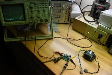
I have included an image of my test setup.
I am not able to get rid of those squiggly signals riding on top of my trace.
I twisted all the wires in my test setup and the scope probes are shielded coax. Moving things around has no effect on the signal.
I lowered Cx from .01uF to .0047uF to reduce the overall amplitude of the signal.
Is it likely that the lower Cx=.0047uf is high enough in capacitance to overcome the capacitance of my transformer inter-winding capacitance(Unknown) and the capacitance presented by the 4 MERF860 diodes in the bridge rectifier on the Salas SSLV 1.3 regulators? I cannot find a specification for the capacitance of the MERF860 diodes.
Attachments
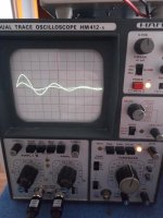
Here is the setup and result with an Avel Lindberg Y236001 torroid.
Cx=.0068uF Cs=.15uF Rs=9.0 Ohm

Cx=.0068uF Cs=.15uF Rs=9.0 Ohm
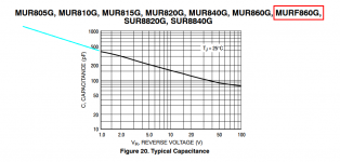
This datasheet shows junction capacitance in one of its Figures; image attached below. I think you can reasonably estimate that diode capacitance at zero bias is in the neighborhood of approximately 1 nanofarad (1000 picofarads).
Super high frequency squiggly lines like you are seeing, are typically artifacts of an imperfect test jig setup, and not properties of the transformer itself. Usually excess inductance in the ground network, especially the scope probe grounds. Slow down the horizontal sweep rate, and slide the whole trace to the left, so that you see the first three or four lumpity bumps when the Rs potentiometer is set to maximum-ohms. Then dial the ohms downward and watch the lumpity bumps gradually disappear. When you get the zeta=1 waveshape, stop dialling. You're done. Ignoring the squiggles.
For optional, not-required, laboratory fun & enjoyment, you could try the experiment below. Usually it reduces the unpleasant squiggles but does not change the main result: Optimum Rs remains the same. This may boost your confidence that it's okay to ignore the squiggles.
Set the scope vertical amplifier to "Bandwidth Limit" and, if available, set the trigger mode to "HF reject". Power the bellringer test jig PCB from a variable output lab power supply. Start with 9.0V on the supply and sloooooowly turn it down all the way to 2.0 volts. You'll need to stop and readjust the trigger level (downward) a few times, as you dial down the supply. Eventually, just before the oscillator stops working and the trace disappears, you'll see the squiggles shrinking. The lumpity bumps don't move, the optimum Rs doesn't change, but the squiggles diminish. That's because they are caused by (L*dI/dt) disturbances, and you are indirectly lowering dI/dt when you lower the supply voltage.
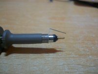
Another way to do it is to securely hold the PCB in a fixed position (I use masking tape but a Panavise could work), have a knowledgeable lab buddy operate the scope & snap the photos, freeing both of your hands and both of your eyes to probe the signal with a super low ground inductance arrangement as shown below. You'll get clean traces even when running Quasimodo from a 15 volt supply. Read Howard Johnson's book High Speed Digital Design: A Handbook Of Black Magic for much much more. HJ is a schoolmate of mine but not a relative.
_
Super high frequency squiggly lines like you are seeing, are typically artifacts of an imperfect test jig setup, and not properties of the transformer itself. Usually excess inductance in the ground network, especially the scope probe grounds. Slow down the horizontal sweep rate, and slide the whole trace to the left, so that you see the first three or four lumpity bumps when the Rs potentiometer is set to maximum-ohms. Then dial the ohms downward and watch the lumpity bumps gradually disappear. When you get the zeta=1 waveshape, stop dialling. You're done. Ignoring the squiggles.
For optional, not-required, laboratory fun & enjoyment, you could try the experiment below. Usually it reduces the unpleasant squiggles but does not change the main result: Optimum Rs remains the same. This may boost your confidence that it's okay to ignore the squiggles.
Set the scope vertical amplifier to "Bandwidth Limit" and, if available, set the trigger mode to "HF reject". Power the bellringer test jig PCB from a variable output lab power supply. Start with 9.0V on the supply and sloooooowly turn it down all the way to 2.0 volts. You'll need to stop and readjust the trigger level (downward) a few times, as you dial down the supply. Eventually, just before the oscillator stops working and the trace disappears, you'll see the squiggles shrinking. The lumpity bumps don't move, the optimum Rs doesn't change, but the squiggles diminish. That's because they are caused by (L*dI/dt) disturbances, and you are indirectly lowering dI/dt when you lower the supply voltage.
Another way to do it is to securely hold the PCB in a fixed position (I use masking tape but a Panavise could work), have a knowledgeable lab buddy operate the scope & snap the photos, freeing both of your hands and both of your eyes to probe the signal with a super low ground inductance arrangement as shown below. You'll get clean traces even when running Quasimodo from a 15 volt supply. Read Howard Johnson's book High Speed Digital Design: A Handbook Of Black Magic for much much more. HJ is a schoolmate of mine but not a relative.
_
Attachments
Last edited:
This datasheet shows junction capacitance in one of its Figures; image attached below. I think you can reasonably estimate that diode capacitance at zero bias is in the neighborhood of approximately 1 nanofarad (1000 picofarads).
Do you think that the use of Cx=.0047uF is too close to estimated
Ct+C rectifier? Would it be best to use a larger cap Cx=.0068uF or the original Cx=.01uF in my application?
If I do so the amplitude of the ring will be increased.
QUOTE][/QUOTE]"Slow down the horizontal sweep rate, and slide the whole trace to the left, so that you see the first three or four lumpity bumps when the Rs potentiometer is set to maximum-ohms. Then dial the ohms downward and watch the lumpity bumps gradually disappear. When you get the zeta=1 waveshape, stop dialling. You're done. Ignoring the squiggles."
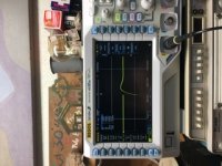
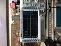
Here is the image of my trace using Cx=.0047uF Cs=.15uF Rs=98.8 Ohm
Peak voltage of that first spike is 500Mv
If I insert Cx=.0068 that spike is about 800mV Peak
If I insert Cx=.01uF it goes up to 1.4v Peak
Here is the image of my trace using Cx=.0047uF Cs=.15uF Rs=98.8 Ohm
Peak voltage of that first spike is 500Mv
If I insert Cx=.0068 that spike is about 800mV Peak
If I insert Cx=.01uF it goes up to 1.4v Peak
Attachments

Super high frequency squiggly lines like you are seeing, are typically artifacts of an imperfect test jig setup, and not properties of the transformer itself. Usually excess inductance in the ground network, especially the scope probe grounds. Slow down the horizontal sweep rate, and slide the whole trace to the left, so that you see the first three or four lumpity bumps when the Rs potentiometer is set to maximum-ohms. Then dial the ohms downward and watch the lumpity bumps gradually disappear. When you get the zeta=1 waveshape, stop dialling. You're done. Ignoring the squiggles.
I wonder why they are not present on the trace when I am testing the Avel torroid as seen in the image in post #1924?
I wonder why they are not present on the trace when I am testing the Avel torroid as seen in the image in post #1924?
Hi tmas,
To answer your question from post #1920 -- 'Yes, sorry. My bad.' 😱
I was mis-remembering Monk55's post #1893, thinking it was yours. Sorry.
I wonder the same thing -- that your Avel toroid dials in just as predicted, but the 400VA unit has the aberration. Looking forward to the answer to that, too -- from somebody a lot smarter than me.😉
Have you tried it without the 2nd probe and its loping ground? You're just using it for Trigger, right?
Regards
Hi Mark.
With a transformer with 2 pair of secondaries while testing pair one the second is shorted. Is the procedure the same if only one pair of secondaries is used while the other pair is not shorted and isolated? I have heard different advice for handling unused secondaries. If not snubbered I would isolate them. What would You do with the unused pair when the other is snubbered?
With a transformer with 2 pair of secondaries while testing pair one the second is shorted. Is the procedure the same if only one pair of secondaries is used while the other pair is not shorted and isolated? I have heard different advice for handling unused secondaries. If not snubbered I would isolate them. What would You do with the unused pair when the other is snubbered?
Have you tried it without the 2nd probe and its loping ground? You're just using it for Trigger, right?
Yes. I have. It made no difference. I tried only one of the grounds and connecting the grounds together.
I bought a TH v4 kit from dsolodov, great kit and packaging! I've spent the last three days testing a pair of Antek transformers, I was able to duplicate my results each day. I'm fairly confident of my results:
Antek AS-0515
50va dual 15v secondaries
Cx = 0.01uf
Cs = 0.15uf
Rs = 50 ohms and 51 ohms on the other secondary
Antek AS-0532
50va dual 32v secondaries
Cx = 0.01uf
Cs = 0.15uf
Rs = 84.4 ohms and 88 ohms
Antek AS-0515
50va dual 15v secondaries
Cx = 0.01uf
Cs = 0.15uf
Rs = 50 ohms and 51 ohms on the other secondary
Antek AS-0532
50va dual 32v secondaries
Cx = 0.01uf
Cs = 0.15uf
Rs = 84.4 ohms and 88 ohms
Attached scope shot set 5Vcm 0,5ms Quasimodo without Rs, it's OK the measurements?
Attachments
Last edited:
- Home
- Amplifiers
- Power Supplies
- Simple, no-math transformer snubber using Quasimodo test-jig