Start with the same cap values, at least. You'll know pretty quick whether or not the approach is needed. I would suspect that it is, since MOSFETS have plenty of Source-Drain capacitance, and its the transformer secondary leakage inductance that Quasi wants to tame.
The input capacitance of the MOSFET should not factor into it -- doesn't the LT4320 provide the Gate drive?
The input capacitance of the MOSFET should not factor into it -- doesn't the LT4320 provide the Gate drive?

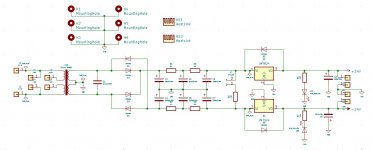
C1 in the attached circuit diagram is .22uF. It is connected between the + and - rail. My question is: How will C1 effect the two snubber circuits? Do I disregard it and install the snubbers between + rail and ground and - rail and ground? Or is C1 actually part of the snubber circuit and if it is, how?
From that schematic, C1 is not connected between the positive and negative rails. C1 is connected across the transformer secondary, before the rectifier. You'll also want the snubber across the secondary, before the rectifier.
Have a look at the Quasimodo pdf, it would normally have answered your questions (specifically pages 5, 6 and 7). It explains that C1 is in fact the snubber's Cx. You'll also get some information about selecting a Cs value.
From what I understand, a center-tap transformer would require 2 snubbers: one between one leg of the secondary and center tap, and a second between the center tap and the second leg of the secondary.
Last edited:
I completely agree with Paul M. Please download the .pdf document attached to post #1 of this thread, and study Figure 13 (page 11), especially the very last one of its five panels. That panel shows the correct snubbing topology for a transformer whose two secondary windings are connected in the "Center Tapped" configuration.
It's also worth reading the entire document, in order to learn the preferred ratio of Cs to Cx; the preferred capacitor vendor and dielectric type; the methodology of actually using a Quasimodo test jig, and dozens of other joyful tidbits.
It's also worth reading the entire document, in order to learn the preferred ratio of Cs to Cx; the preferred capacitor vendor and dielectric type; the methodology of actually using a Quasimodo test jig, and dozens of other joyful tidbits.
Paul, you are right, I called the connections wrong, not the rails, the secondary windings. I'll remove C1 and see how I can modify the board to get two sets of snubbers from secondary to center twice.
I read the attachment, C1 through me by being attached across the secondary windings and not from secondary to center twice. After I woke up this morning it came to me and made sense, had to sleep on it I guess. The board isn't made for this, but pretty sure I can modify it to fit the two snubbers.
Thanks Paul and Mark for your answers!
Thanks Paul and Mark for your answers!
PCB manufacture
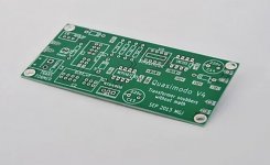
Mark, I'm successfully sidetracked on another project. Thanks for this. My question is, can I send one of the Gerber files to JLCPCB? v4, TH. Nice to see this thread is still alive. Thanks,
Don
Mark, I'm successfully sidetracked on another project. Thanks for this. My question is, can I send one of the Gerber files to JLCPCB? v4, TH. Nice to see this thread is still alive. Thanks,
Don
I think the probability of success will be at least 97%, if you try the experiment. You could also look at the Gerber data on your computer before uploading to JLCPCB; the viewer at http://www.pcbxprt.com is 100% free software and runs completely inside your browser -- no software installs, no demands for your email address. Then, after you've uploaded the Gerber data to JLCPCB's website, but before you've paid by credit card, look at it again with their Gerber viewing window. Check to see whether their view of the PCB data is sensible or crazy.
If that doesn't reassure you, and if you're still worried that your $22.70 might buy you ten fatally flawed & useless boards with 7 day delivery, fire up the Googles. Over the years I've noticed a few commercial businesses who sell Quasimodo PCBs in qty=1, from websites. You'll pay more, per board, but now you have somebody's assurance that the board has been fabbed correctly.
Better yet, broadcast a message here on this thread: WANTED TO BUY, 1 thru hold Quasimodo PCB, shipping to USA. There may be a few members who ordered ten boards from fab, and would be glad to get rid of their extras.
timid
Mark,
I started to think about it and said what the heck- give it a try. Nothing ventured nothing gained. So I did. It loaded right in and nothing looked weird. so I ordered it. It's on the way. When I get them, if all looks OK, I will have three boards I will gladly give-a-way free to anybody that wants one. Including freight for US. A mini thank you to all that help I get.
Thank you.
Don
I haven’t yet got myself an oscilloscope, so if anyone in europe has a spare pcb, I‘d gladly take it.
Pm please?
David
Pm please?
David
scopes
Speaking of scopes. I am looking at the Sigilent SDS1052DL +50MHz storage.
It is dual channel. Does anybody know of a reason this scope wouldn't be good for DIY audio in general. Including Quasimodo.
Thanks,
Don
Speaking of scopes. I am looking at the Sigilent SDS1052DL +50MHz storage.
It is dual channel. Does anybody know of a reason this scope wouldn't be good for DIY audio in general. Including Quasimodo.
Thanks,
Don
I have a Siglent SDS2304X that I like pretty well. The probes are junk, but they can be replaced in time. I think you'll like the Siglent.
I do recommend this article by Limor Fried on scope bandwidth. If, after reading it, you're satisfied with the 50mHz, then that's awesome. It may work well for you, and if so, can save you a ton of money. I use mine for more than audio, so I wanted a little more bandwidth.
Have fun with it!
I do recommend this article by Limor Fried on scope bandwidth. If, after reading it, you're satisfied with the 50mHz, then that's awesome. It may work well for you, and if so, can save you a ton of money. I use mine for more than audio, so I wanted a little more bandwidth.
Have fun with it!
I should've added - I got a bunch done for a few years with a Hantek scope not half as nice as the scope you're looking at, including snubbing transformers with the Quasimodo.
You'll do just fine.
You'll do just fine.
Hello David,
those modern fully digital scopes do have their merits and provide a lot of functionality! But if you're constrained for money or are a measurements beginner, a used HAMEG e.g. 50MHz analog or analog/digital scope may be a good first step. For Quasimodo measurements this would be clearly sufficient!
just for consideration...
Greetings,
Winfried
Hello David,
those modern fully digital scopes do have their merits and provide a lot of functionality! But if you're constrained for money or are a measurements beginner, a used HAMEG e.g. 50MHz analog or analog/digital scope may be a good first step. For Quasimodo measurements this would be clearly sufficient!
just for consideration...
Greetings,
Winfried
Thanks many much times, wgh52!
I indeed already rushed into the bitscope-website propagating digital stuff (to run on the computer), since this other recommendation here is a bit over my head/budget...
I anyway won‘t start this subproject right away, so there’s no hurry [emoji3526]
- Home
- Amplifiers
- Power Supplies
- Simple, no-math transformer snubber using Quasimodo test-jig
